“SAI device tree configuration”的版本间的差异
Zhouyuebiao(讨论 | 贡献) |
|||
| (未显示2个用户的6个中间版本) | |||
| 第1行: | 第1行: | ||
| − | |||
| − | [[ | + | == Article purpose == |
| − | + | 本文介绍如何在将 [[SAI internal peripheral]] 分配给 '''Linux<sup>®</sup> OS'''时对其进行配置。在这种情况下,它由 [[ALSA_overview|ALSA framework]]控制。 | |
| − | + | ||
| + | 使用[[Device_tree|device tree]] 机制执行配置,该机制提供由[[SAI_Linux_driver|SAI linux driver]]使用的SAI外围设备的硬件描述。 | ||
| + | |||
| + | 如果外围设备已分配给另一个执行上下文,请参阅 [[How to assign an internal peripheral to a runtime context]] 文章,以获取有关外围设备分配和配置的准则。 | ||
| + | |||
| + | == DT bindings documentation == | ||
| + | STM32 SAI设备树绑定 <ref name="sai bindings">[https://www.kernel.org/doc/Documentation/devicetree/bindings/sound/st%2Cstm32-sai.txt STM32 SAI bindings]</ref> 本文档介绍了所有必需的和可选的配置属性。 | ||
| + | |||
| + | == DT configuration == | ||
| + | 该硬件描述是'''STM32微处理器'''设备树文件(扩展名为.dtsi)和'''板子'''设备树文件(扩展名为.dts)的组合。 有关设备树文件分割的说明,请参见[[Device tree]]。<br> | ||
| + | 通过Linux <sup>®</sup> 内核ALSA框架,SAI用作声卡的组件。 与声卡相关的设备树节点在[[#DT_configuration_.28board_level.29|board device tree]]中进行了描述。 | ||
| + | |||
| + | STM32 SAI外设包括两个共享公共资源的独立音频子块。 | ||
| + | SAI设备树节点反映了这种体系结构,如下面的SAI DT示例所示。 | ||
| + | {{ | ||
| + | ImageMap| | ||
| + | Image:Sai_configuration.png {{!}} frame {{!}} center{{!}} SAI device tree configuration | ||
| + | rect 4 135 158 404 [[Clock_overview]] | ||
| + | rect 625 222 764 403 [[Pinctrl_overview]] | ||
| + | }} | ||
| + | |||
| + | &saix { | ||
| + | {{highlight|/* SAIx parent node. Configure common ressources */}} | ||
| + | clock-names = "pclk", "x8k", "x11k"; {{highlight|/* Peripheral and parent clock configuration. */}} | ||
| + | ... | ||
| + | |||
| + | saixa { | ||
| + | {{highlight|/* child node. Configure ressources dedicated to SAIxA subblock */}} | ||
| + | clock-names = "sai_ck"; {{highlight|/* SAIxA kernel clock confguration. */}} | ||
| + | pinctrl-names = "default"; {{highlight|/* GPIOsA configuration. */}} | ||
| + | ... | ||
| + | }; | ||
| + | |||
| + | saixb { | ||
| + | {{highlight|/* child node. Configure ressources dedicated to SAIxB subblock */}} | ||
| + | clock-names = "sai_ck"; {{highlight|/* SAIxB kernel clock confguration. */}} | ||
| + | pinctrl-names = "default"; {{highlight|/* GPIOsB configuration. */}} | ||
| + | ... | ||
| + | }; | ||
| + | }; | ||
| + | |||
| + | '''STM32CubeMX''' 可用于生成板卡设备树。有关更多详细信息,请参考[[#How_to_configure_the_DT_using_STM32CubeMX|How to configure the DT using STM32CubeMX]]。 | ||
| + | |||
| + | === DT configuration (STM32 level) === | ||
| + | SAI节点在STM32微处理器设备树中声明。它们描述了硬件参数,例如寄存器地址,中断和DMA。 对于给定的STM32MPU,这组属性可能不会改变。 对于STM32MP1,对应的DT文件为stm32mp157c.dtsi <ref name="stm32mp157c.dtsi">{{CodeSource | Linux kernel | arch/arm/boot/dts/stm32mp157c.dtsi}}</ref>. | ||
| + | {{Warning|该设备树部分与STM32微处理器有关。它应保持原样,而不应由最终用户修改。}} | ||
| + | |||
| + | === DT configuration (board level) === | ||
| + | |||
| + | SAI配置是否取决于板,是否连接到外部组件(例如音频编解码器)。 SAI与其他组件之间的链接定义了声卡。 必须在主板设备树中配置此声卡。有关各种STM32MPU板上SAI配置的示例,请参考[[Soundcard configuration|soundcard configuration]]。 | ||
| + | |||
| + | === DT configuration examples === | ||
| + | |||
| + | 本章详细介绍高级SAI配置。 这些示例基于 [[:Category:Getting_started_with_STM32MP1_boards|STM32MP1 boards]] SAI用例。 相应的设备树可以在 [[Soundcard configuration|soundcard]] 文章中找到。 | ||
| + | {{Info|在本章中,“ SAI”代表SAI子块SAIxA或SAIxB.}} | ||
| + | |||
| + | ==== Setting SAI as a master clock provider ==== | ||
| + | SAI外设可以通过mclk输出引脚为外部组件 (例如编解码器)提供时钟。 在这种情况下,它充当主时钟(mclk)提供程序。下面的DT示例提供了一个作为mclk provider的SAI配置示例。 | ||
| + | 在此示例中,编解码器驱动程序支持基于ASoC DAPM机制的mclk输入。 | ||
| + | 如果不是这种情况,则必须调整编解码器驱动程序。这可以通过将DAPM时钟供应小部件添加到编解码器驱动程序来实现。 所需的DAPM时钟供应小部件的示例可以在Cirrus CS42L51编解码器源代码<ref name="CS42L51 code">{{CodeSource | Linux kernel | sound/soc/codecs/cs42l51.c}}</ref>. | ||
| + | 在下面的设备树示例中,编解码器DAPM时钟窗口小部件名为“MCLKX”。 | ||
| + | |||
| + | 为了允许mclk激活/停用,必须在DT中定义DAPM路由。此路由在sound节点中定义,如下所示。 | ||
| + | |||
| + | soundcard { | ||
| + | routing = | ||
| + | "Playback" , "MCLKX", {{highlight|/* Set a route between "MCLKX" and "playback" widgets */}} | ||
| + | "Capture" , "MCLKX"; | ||
| + | ... | ||
| + | }; | ||
| + | |||
| + | codec: { | ||
| + | clocks = <&sai2a>; {{highlight|/* The codec is a consumer of SAI2A master clock */}} | ||
| + | clock-names = "MCLKX"; {{highlight|/* Feed MCLKX codec clock with SAI2A master clock provider */}} | ||
| + | ... | ||
| + | }; | ||
| + | |||
| + | &sai2 { | ||
| + | ... | ||
| + | |||
| + | sai2a: audio-controller@4400b004 { | ||
| + | #clock-cells = <0>; {{highlight|/* Set SAI2A as master clock provider */}} | ||
| + | ... | ||
| + | sai2a_endpoint: endpoint { | ||
| + | mclk-fs = <256>; {{highlight|/* Set mclk/fs ratio. (256 or 512) */}} | ||
| + | }; | ||
| + | }; | ||
| + | }; | ||
| + | |||
| + | ==== Sharing master clock between two SAIs ==== | ||
| + | |||
| + | 将SAI设置为主时钟提供者时,另一个SAI可以共享该主时钟。 | ||
| + | 这可以通过通过DT配置将SAI设置为mclk使用者来实现。 | ||
| + | 这意味着mclk使用者SAI可以请求根据其自己的音频流采样率更改mclk速率。 | ||
| + | 这意味着当使用两个SAI子块时,音频采样率必须相同。 | ||
| + | |||
| + | &sai2 { | ||
| + | ... | ||
| + | |||
| + | sai2a: audio-controller@4400b004 { | ||
| + | #clock-cells = <0>; {{highlight|/* Set SAI2A as master clock provider */}} | ||
| + | ... | ||
| + | }; | ||
| + | |||
| + | sai2b: audio-controller@4400b024 { | ||
| + | clocks = <&rcc SAI2_K>, <&sai2a>; {{highlight|/* SAI2B is a consumer of SAI2A master clock */}} | ||
| + | clock-names = "sai_ck", "MCLK"; {{highlight|/* Feed SAI2B MCLK clock with SAI2A master clock provider */}} | ||
| + | ... | ||
| + | sai2b_endpoint: endpoint { | ||
| + | mclk-fs = <256>; {{highlight|/* Set mclk/fs ratio. (256 or 512) */}} | ||
| + | }; | ||
| + | }; | ||
| + | }; | ||
| + | |||
| + | ==== Sharing the codec interface between two SAIs ==== | ||
| + | |||
| + | 通过共享I2S总线(即FS和SCK时钟),两个SAI可以连接到同一编解码器接口。 | ||
| + | |||
| + | [[Image:sai_shared_codec.png {{!}} frame {{!}} center{{!}} SAIs sharing the same codec interface|link=]] | ||
| + | |||
| + | 在这种情况下: | ||
| + | *编解码器必须是I2S总线上的主机。 | ||
| + | *总线时钟仅连接一个SAI。 另一个SAI必须配置为连接到总线的SAI的从设备。 | ||
| + | *I2S总线 I/O 引脚必须在父级进行管理,以便无论正在运行的SAI如何激活相应的引脚。 | ||
| + | |||
| + | 从ASoC的角度来看:<BR> | ||
| + | 必须将两个CPU DAI连接到同一编解码器DAI。 ASoC音频图形卡本身不支持这种拓扑。 实际上,当音频图形卡解析编解码器节点时,它期望找到与端点索引匹配的DAI接口索引。 一种解决方法是在编解码器驱动程序中实现of_xlate_dai_id回调,以允许对两个端点使用相同的DAI接口。可以在下面或在Cirrus CS42L51编解码器源代码中找到代码示例。<ref name="CS42L51 code">{{CodeSource | Linux kernel | sound/soc/codecs/cs42l51.c}}</ref>. | ||
| + | |||
| + | * 代码示例 | ||
| + | |||
| + | <syntaxhighlight lang="c"> | ||
| + | static int codec_of_xlate_dai_id(struct snd_soc_component *component, | ||
| + | struct device_node *endpoint) | ||
| + | { | ||
| + | /* return dai id 0, whatever the endpoint index */ | ||
| + | return 0; | ||
| + | } | ||
| + | </syntaxhighlight> | ||
| + | |||
| + | * DT example | ||
| + | |||
| + | codec { | ||
| + | ... | ||
| + | codec_port { | ||
| + | codec_tx_endpoint { | ||
| + | remote-endpoint = <&sai2a_endpoint>; | ||
| + | frame-master; {{highlight|/* Set codec as master of SAI2A for FS clock. */}} | ||
| + | bitclock-master; {{highlight|/* Set codec as master of SAI2A for SCK clock. */}} | ||
| + | }; | ||
| + | |||
| + | codec_rx_endpoint { {{highlight|/* Second endpoint mapped on codec DAI 0 via of_xlate */}} | ||
| + | remote-endpoint = <&sai2b_endpoint>; | ||
| + | frame-master; {{highlight|/* Set codec as master of SAI2B for FS clock. */}} | ||
| + | bitclock-master; {{highlight|/* Set codec as master of SAI2B for SCK clock. */}} | ||
| + | }; | ||
| + | }; | ||
| + | }; | ||
| + | |||
| + | &sai2 { | ||
| + | pinctrl-names = "default", "sleep"; {{highlight|/* Defines SAI2A/B GPIOs at parent level. */}} | ||
| + | pinctrl-0 = <&sai2a_pins_a>, <&sai2b_pins_b>; | ||
| + | pinctrl-1 = <&sai2a_sleep_pins_a>, <&sai2b_sleep_pins_b>; | ||
| + | ... | ||
| + | |||
| + | sai2a: audio-controller@4400b004 { | ||
| + | remote-endpoint = <&codec_tx_endpoint>; | ||
| + | ... | ||
| + | }; | ||
| + | |||
| + | sai2b: audio-controller@4400b024 { | ||
| + | remote-endpoint = <&codec_rx_endpoint>; | ||
| + | st,sync = <&sai2a 2>; {{highlight|/* Set SAI2B as slave of SAI2A. */}} | ||
| + | }; | ||
| + | }; | ||
| + | |||
| + | ==How to configure the DT using STM32CubeMX== | ||
| + | [[STM32CubeMX]] 工具可用于配置STM32MPU设备并获取相应的[[Device_tree#STM32|platform configuration device tree]] 文件。<br /> | ||
| + | STM32CubeMX可能不支持上述 [[#DT bindings documentation|DT bindings documentation]] 段落中描述的所有属性。 如果是这样,该工具会在生成的设备树中插入 '''用户部分''' 。然后可以编辑这些部分以添加一些属性,并将它们一代一代地保留下来。 有关更多信息,请参见[[STM32CubeMX]]用户手册。 | ||
| + | {{Warning|STM32CubeMX不允许生成配置声卡所需的所有节点。 声卡节点和编解码器节点必须通过用户部分手动填充。}} | ||
| + | |||
| + | ==References== | ||
| + | <references /> | ||
2020年11月5日 (四) 15:56的最新版本
目录
Article purpose
本文介绍如何在将 SAI internal peripheral 分配给 Linux® OS时对其进行配置。在这种情况下,它由 ALSA framework控制。
使用device tree 机制执行配置,该机制提供由SAI linux driver使用的SAI外围设备的硬件描述。
如果外围设备已分配给另一个执行上下文,请参阅 How to assign an internal peripheral to a runtime context 文章,以获取有关外围设备分配和配置的准则。
DT bindings documentation
STM32 SAI设备树绑定 [1] 本文档介绍了所有必需的和可选的配置属性。
DT configuration
该硬件描述是STM32微处理器设备树文件(扩展名为.dtsi)和板子设备树文件(扩展名为.dts)的组合。 有关设备树文件分割的说明,请参见Device tree。
通过Linux ® 内核ALSA框架,SAI用作声卡的组件。 与声卡相关的设备树节点在board device tree中进行了描述。
STM32 SAI外设包括两个共享公共资源的独立音频子块。 SAI设备树节点反映了这种体系结构,如下面的SAI DT示例所示。
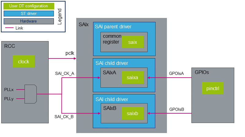
&saix {
	/* SAIx parent node. Configure common ressources  */
	clock-names = "pclk", "x8k", "x11k"; /* Peripheral and parent clock configuration.  */
	...

	saixa {
		/* child node. Configure ressources dedicated to SAIxA subblock */
		clock-names = "sai_ck"; /* SAIxA kernel clock confguration.  */
		pinctrl-names = "default"; /* GPIOsA configuration.  */
		...
	};

	saixb {
		/* child node. Configure ressources dedicated to SAIxB subblock */
		clock-names = "sai_ck"; /* SAIxB kernel clock confguration.  */
		pinctrl-names = "default"; /* GPIOsB configuration.  */
		...
	};
};
STM32CubeMX 可用于生成板卡设备树。有关更多详细信息,请参考How to configure the DT using STM32CubeMX。
DT configuration (STM32 level)
SAI节点在STM32微处理器设备树中声明。它们描述了硬件参数,例如寄存器地址,中断和DMA。 对于给定的STM32MPU,这组属性可能不会改变。 对于STM32MP1,对应的DT文件为stm32mp157c.dtsi [2].
| 该设备树部分与STM32微处理器有关。它应保持原样,而不应由最终用户修改。 |
DT configuration (board level)
SAI配置是否取决于板,是否连接到外部组件(例如音频编解码器)。 SAI与其他组件之间的链接定义了声卡。 必须在主板设备树中配置此声卡。有关各种STM32MPU板上SAI配置的示例,请参考soundcard configuration。
DT configuration examples
本章详细介绍高级SAI配置。 这些示例基于 STM32MP1 boards SAI用例。 相应的设备树可以在 soundcard 文章中找到。
| 在本章中,“ SAI”代表SAI子块SAIxA或SAIxB. |
Setting SAI as a master clock provider
SAI外设可以通过mclk输出引脚为外部组件 (例如编解码器)提供时钟。 在这种情况下,它充当主时钟(mclk)提供程序。下面的DT示例提供了一个作为mclk provider的SAI配置示例。 在此示例中,编解码器驱动程序支持基于ASoC DAPM机制的mclk输入。 如果不是这种情况,则必须调整编解码器驱动程序。这可以通过将DAPM时钟供应小部件添加到编解码器驱动程序来实现。 所需的DAPM时钟供应小部件的示例可以在Cirrus CS42L51编解码器源代码[3]. 在下面的设备树示例中,编解码器DAPM时钟窗口小部件名为“MCLKX”。
为了允许mclk激活/停用,必须在DT中定义DAPM路由。此路由在sound节点中定义,如下所示。
soundcard {
	routing =
		"Playback" , "MCLKX", /* Set a route between "MCLKX" and "playback" widgets */
		"Capture" , "MCLKX";
	...
};

codec: {
	clocks = <&sai2a>;     /* The codec is a consumer of SAI2A master clock */
	clock-names = "MCLKX"; /* Feed MCLKX codec clock with SAI2A master clock provider */
	...
};

&sai2 {
	...

	sai2a: audio-controller@4400b004 {
		#clock-cells = <0>; /* Set SAI2A as master clock provider */
		...
		sai2a_endpoint: endpoint {
			mclk-fs = <256>; /* Set mclk/fs ratio. (256 or 512) */
		};
	};
};
Sharing master clock between two SAIs
将SAI设置为主时钟提供者时,另一个SAI可以共享该主时钟。 这可以通过通过DT配置将SAI设置为mclk使用者来实现。 这意味着mclk使用者SAI可以请求根据其自己的音频流采样率更改mclk速率。 这意味着当使用两个SAI子块时,音频采样率必须相同。
&sai2 {
	...

	sai2a: audio-controller@4400b004 {
		#clock-cells = <0>; /* Set SAI2A as master clock provider */
		...
	};

	sai2b: audio-controller@4400b024 {
		clocks = <&rcc SAI2_K>, <&sai2a>; /* SAI2B is a consumer of SAI2A master clock */
		clock-names = "sai_ck", "MCLK";   /* Feed SAI2B MCLK clock with SAI2A master clock provider */
		...
		sai2b_endpoint: endpoint {
			mclk-fs = <256>; /* Set mclk/fs ratio. (256 or 512) */
		};
	};
};
Sharing the codec interface between two SAIs
通过共享I2S总线(即FS和SCK时钟),两个SAI可以连接到同一编解码器接口。
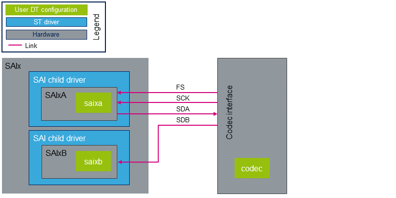
在这种情况下:
- 编解码器必须是I2S总线上的主机。
- 总线时钟仅连接一个SAI。 另一个SAI必须配置为连接到总线的SAI的从设备。
- I2S总线 I/O 引脚必须在父级进行管理,以便无论正在运行的SAI如何激活相应的引脚。
从ASoC的角度来看:
必须将两个CPU DAI连接到同一编解码器DAI。 ASoC音频图形卡本身不支持这种拓扑。 实际上,当音频图形卡解析编解码器节点时,它期望找到与端点索引匹配的DAI接口索引。 一种解决方法是在编解码器驱动程序中实现of_xlate_dai_id回调,以允许对两个端点使用相同的DAI接口。可以在下面或在Cirrus CS42L51编解码器源代码中找到代码示例。[3].
- 代码示例
static int codec_of_xlate_dai_id(struct snd_soc_component *component,
				   struct device_node *endpoint)
{
	/* return dai id 0, whatever the endpoint index */
	return 0;
}
- DT example
codec {
	...
	codec_port {
		codec_tx_endpoint {
			remote-endpoint = <&sai2a_endpoint>;
			frame-master;    /* Set codec as master of SAI2A for FS clock. */
			bitclock-master; /* Set codec as master of SAI2A for SCK clock. */
		};

		codec_rx_endpoint { /* Second endpoint mapped on codec DAI 0 via of_xlate */
			remote-endpoint = <&sai2b_endpoint>;
			frame-master;    /* Set codec as master of SAI2B for FS clock. */
			bitclock-master; /* Set codec as master of SAI2B for SCK clock. */
		};
	};
};

&sai2 {
	pinctrl-names = "default", "sleep"; /* Defines SAI2A/B GPIOs at parent level. */
	pinctrl-0 = <&sai2a_pins_a>, <&sai2b_pins_b>;
	pinctrl-1 = <&sai2a_sleep_pins_a>, <&sai2b_sleep_pins_b>;
	...

	sai2a: audio-controller@4400b004 {
		remote-endpoint = <&codec_tx_endpoint>;
		...
	};

	sai2b: audio-controller@4400b024 {
		remote-endpoint = <&codec_rx_endpoint>;
		st,sync = <&sai2a 2>; /* Set SAI2B as slave of SAI2A. */
	};
};
How to configure the DT using STM32CubeMX
STM32CubeMX 工具可用于配置STM32MPU设备并获取相应的platform configuration device tree 文件。
STM32CubeMX可能不支持上述 DT bindings documentation 段落中描述的所有属性。 如果是这样,该工具会在生成的设备树中插入 用户部分 。然后可以编辑这些部分以添加一些属性,并将它们一代一代地保留下来。 有关更多信息,请参见STM32CubeMX用户手册。
| STM32CubeMX不允许生成配置声卡所需的所有节点。 声卡节点和编解码器节点必须通过用户部分手动填充。 |