“Soundcard configuration”的版本间的差异
| (未显示同一用户的4个中间版本) | |||
| 第68行: | 第68行: | ||
=== Static configuration === | === Static configuration === | ||
| − | + | 以下摘录来自STM32MP15评估板设备树。这里仅显示与声卡关联的节点以及最相关的属性。例如,使用{{green|green}}字体强调链接节点以形成第一个DAI链接的属性。 | |
/ * '''SOUNDCARD''' */ | / * '''SOUNDCARD''' */ | ||
| 第333行: | 第333行: | ||
}; | }; | ||
| − | + | 用于STMP32MP15评估板的特定于卡的alsa-lib配置文件为/usr/share/alsa/cards/STM32MP1EV.conf。 | |
=== Dynamic configuration === | === Dynamic configuration === | ||
| − | + | 下表概述了允许配置STM32MPU评估板“sound”声卡的控件。 | |
{| class="st-table" | {| class="st-table" | ||
| 第363行: | 第363行: | ||
==== Wolfson wm8994 output configuration ==== | ==== Wolfson wm8994 output configuration ==== | ||
| − | : | + | :在wm8994编解码器上的控制命令,将aif1接口配置为耳机输出(HPOUT1L/R)路径: |
<div style="margin-left: 2em;"> | <div style="margin-left: 2em;"> | ||
| 第377行: | 第377行: | ||
</div> | </div> | ||
| − | : | + | :在wm8994编解码器上的控制命令,用于将aif1接口配置为扬声器输出(SPKOUTL/RP)路径: |
<div style="margin-left: 2em;"> | <div style="margin-left: 2em;"> | ||
| 第400行: | 第400行: | ||
==== Wolfson wm8994 input configuration ==== | ==== Wolfson wm8994 input configuration ==== | ||
| − | : | + | :在wm8994编解码器上的控制命令,用于将耳机麦克风输入(IN1LN)配置为aif2接口: |
<div style="margin-left: 2em;"> | <div style="margin-left: 2em;"> | ||
| 第426行: | 第426行: | ||
==== SPDFIRX input configuration ==== | ==== SPDFIRX input configuration ==== | ||
| − | : | + | :用于在SPDFIRX上配置rx1输入路径的控制命令: |
<div style="margin-left: 2em;"> | <div style="margin-left: 2em;"> | ||
| 第438行: | 第438行: | ||
{{ | {{ | ||
ImageMap| | ImageMap| | ||
| − | Image:Mp15_dk_main_soundcard.png {{!}} frame {{!}} center{{!}} STM32MP15 Disco | + | Image:Mp15_dk_main_soundcard.png {{!}} frame {{!}} center{{!}} STM32MP15 Disco 主板声卡 |
rect 187 154 256 202 [[SAI internal peripheral]] | rect 187 154 256 202 [[SAI internal peripheral]] | ||
rect 187 252 256 300 [[SAI internal peripheral]] | rect 187 252 256 300 [[SAI internal peripheral]] | ||
| 第451行: | 第451行: | ||
=== Static configuration === | === Static configuration === | ||
| − | + | 下面摘录自STM32MP15 DISCO主板设备树。 此处仅显示与声卡关联的节点以及最相关的属性。例如,使用{{green|green}}字体强调链接节点以形成第一DAI链接的属性。 | |
| − | |||
/ { | / { | ||
/ * '''SOUNDCARD''' */ | / * '''SOUNDCARD''' */ | ||
| 第585行: | 第584行: | ||
}; | }; | ||
| − | + | STMP32MP15 Disco板的特定于卡的alsa-lib配置文件为/usr/share/alsa/cards/STM32MP1DK.conf | |
=== Dynamic configuration === | === Dynamic configuration === | ||
| − | + | 下表概述了允许配置STM32MPU DISCO主板声卡的控件。 | |
{| class="st-table" | {| class="st-table" | ||
| 第611行: | 第610行: | ||
==== Cirrus cs42l51 output configuration ==== | ==== Cirrus cs42l51 output configuration ==== | ||
| − | : | + | :控制命令,用于在cs42l51编解码器上将aif接口配置为耳机输出(AOUTA / B)路径: |
<div style="margin-left: 2em;"> | <div style="margin-left: 2em;"> | ||
| 第622行: | 第621行: | ||
==== Cirrus cs42l51 input configuration ==== | ==== Cirrus cs42l51 input configuration ==== | ||
| − | : | + | :控制命令,用于在cs42l51编解码器上将耳机麦克风输入(MICIN1 / AIN3A)配置到aif接口: |
<div style="margin-left: 2em;"> | <div style="margin-left: 2em;"> | ||
2020年11月5日 (四) 16:33的最新版本
目录
Overview
本文介绍了如何在将ST音频外围设备以及分配给Linux® OS的外部音频组件以及 STM32MP1 boards 时进行配置。 在这种情况下,它们由ALSA框架控制。
在ALSA framework的ASoC层中,音频硬件组件被描述为CPU DAIs and codec,它们链接在一起以创建DAI链接。声卡是收集一组DAI链接的软件组件。 以下STM32 MPU板的每个部分都描述了一个或多个声卡。 提供了每个声卡的示意图,以及其静态和动态配置的方式。
Sound card schematic
声卡原理图概述了构成声卡的硬件和软件组件及其关系。
下面给出的示例声卡示意图强调了声卡和设备树部分之间的链接。
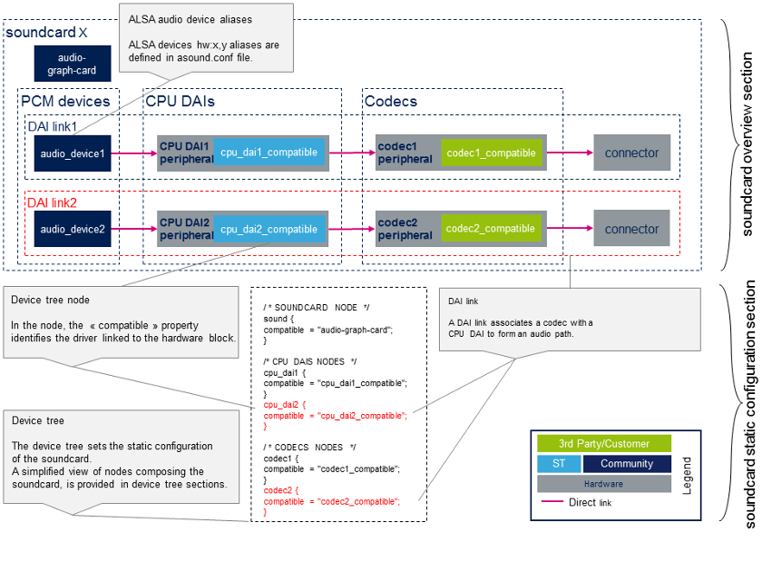
Static configuration
- Device tree
设备树允许描述,配置和连接音频硬件组件以定义声卡。用户必须遵循音频图形卡绑定[1] 来配置声卡和设备图绑定[2] 来连接音频组件。 用户还必须参考音频组件(编解码器和CPU DAI)绑定,以正确配置这些组件。 音频组件的绑定可以在以下各节的设备树样本中以及References chapter中找到。
STMicroelectronics组态工具 STM32CubeMX, 允许生成CPU DAI设备树节点。
| STM32CubeMX不允许配置声卡和编解码器节点,这取决于板。声卡节点和编解码器节点必须通过用户部分手动填充。 |
- asound.conf [3]
可选的asound.conf[3] 系统全局自定义设置文件提供了额外的功能,例如路由和音频样本转换。可以在/ etc目录中找到它。
- 声卡配置文件[3]
alsa-lib层在 /usr/share/alsa/cards 目录中提供卡配置文件。 这些文件允许在标准设备(例如"front", "hdmi" 或 "iec958"设备)上映射ALSA硬件设备。声卡设备树节点中定义的标签定义了卡的名称。 根据 /usr/share/alsa/cards/aliases.conf 映射,从此卡名称中检索卡配置。
STM32MP15 evaluation board sound card configuration
Sound card overview
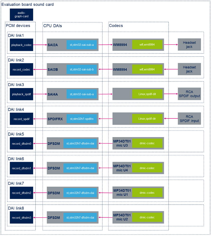
Static configuration
以下摘录来自STM32MP15评估板设备树。这里仅显示与声卡关联的节点以及最相关的属性。例如,使用green字体强调链接节点以形成第一个DAI链接的属性。
/ * SOUNDCARD */
	sound {
		compatible = "audio-graph-card[1]";
		label = "STM32MP1-EV";			/* Sound card identified as STM32MP1EV in ALSA */
		routing =
			"AIF1CLK" , "MCLK1",
			"AIF2CLK" , "MCLK1",
			"IN1LN" , "MICBIAS2",
			"DMIC2DAT" , "MICBIAS1",
			"DMIC1DAT" , "MICBIAS1";
		dais = <&sai2a_port &sai2b_port &sai4a_port &spdifrx_port
			&dfsdm0_port &dfsdm1_port &dfsdm2_port &dfsdm3_port>;
	};

/ * CODECS */
	spdif_out: spdif-out {
		compatible = "linux,spdif-dit[4]";

		spdif_out_port: port@0 {
			spdif_out_endpoint: endpoint {
				remote-endpoint = <&sai4a_endpoint>;
			};
		};
	};

	spdif_in: spdif-in {
		compatible = "linux,spdif-dir[5]";
		spdif_in_port: port@0 {
			spdif_in_endpoint: endpoint {
				remote-endpoint = <&spdifrx_endpoint>;
			};
		};
	};

	dmic0: dmic@0 {
		compatible = "dmic-codec";
		port {
			dmic0_endpoint: endpoint {
				remote-endpoint = <&dfsdm_endpoint0>;
			};
		};
	};

	dmic1: dmic@1 {
		compatible = "dmic-codec";
		port {
			dmic1_endpoint: endpoint {
				remote-endpoint = <&dfsdm_endpoint1>;
			};
		};
	};

	dmic2: dmic@2 {
		compatible = "dmic-codec";
		port {
			dmic2_endpoint: endpoint {
				remote-endpoint = <&dfsdm_endpoint2>;
			};
		};
	};

	dmic3: dmic@3 {
		compatible = "dmic-codec";
		port {
			dmic3_endpoint: endpoint {
				remote-endpoint = <&dfsdm_endpoint3>;
			};
		};
	};
};

&i2c2 {
	wm8994: wm8994@1b {
		compatible = "wlf,wm8994";
		...
		clocks = <&sai2a>;
		clock-names = "MCLK1";

		ports {
			#address-cells = <1>;
			#size-cells = <0>;

			wm8994_tx_port: port@0 {
				wm8994_tx_endpoint: endpoint {
					remote-endpoint = <&sai2a_endpoint>;
				};
			};

			wm8994_rx_port: port@1 {
				wm8994_rx_endpoint: endpoint {
					remote-endpoint = <&sai2b_endpoint>;
				};
			};
		};
	};
};

/* CPU DAIS */
&sai2 {
	clocks = <&rcc SAI2>, <&rcc PLL3_Q>, <&rcc PLL4_Q>;
	pinctrl-names = "default", "sleep";
	pinctrl-0 = <&sai2a_pins_a>, <&sai2b_pins_a>;
	pinctrl-1 = <&sai2a_sleep_pins_a>, <&sai2b_sleep_pins_a>;
	clock-names = "pclk", "x8k", "x11k";

	sai2a: audio-controller@4400b004 {
		compatible = "st,stm32-sai-sub-a";
		dma-names = "tx";				/* SAI set as transmitter */
		clocks = <&rcc SAI2_K>;
		clock-names = "sai_ck";

		sai2a_port: port@0 {
			sai2a_endpoint: endpoint {
				remote-endpoint = <&wm8994_tx_endpoint>;
				format = "i2s";
				mclk-fs = <256>;		/* SAI is master clock provider */
			};
		};
	};

	sai2b: audio-controller@4400b024 {
		compatible = "st,stm32-sai-sub-b";
		dma-names = "rx";				/* SAI set as receiver */
		clocks = <&rcc SAI2_K>, <&sai2a>;
		clock-names = "sai_ck", "MCLK";

		sai2b_port: port@0 {
			sai2b_endpoint: endpoint {
				remote-endpoint = <&wm8994_rx_endpoint>;
				format = "i2s";
				mclk-fs = <256>;		/* SAI is master clock provider */
			};
		};
	};
};

&sai4 {
	clocks = <&rcc SAI4>, <&rcc PLL3_Q>, <&rcc PLL4_Q>;
	clock-names = "pclk", "x8k", "x11k";

	sai4a: audio-controller@50027004 {
		compatible = "st,stm32-sai-sub-a";
		dma-names = "tx";
		st,iec60958;					/* SAI configured for S/PDIF protocol*/
		pinctrl-names = "default", "sleep";
		pinctrl-0 = <&sai4a_pins_a>;
		pinctrl-1 = <&sai4a_sleep_pins_a>;
 		clocks = <&rcc SAI4_K>;
		clock-names = "sai_ck";

		sai4a_port: port@0 {
			sai4a_endpoint: endpoint {
				remote-endpoint = <&spdif_out_endpoint>;
			};
		};
	};
};

&spdifrx {
 	compatible = "st,stm32h7-spdifrx";
 	pinctrl-names = "default", "sleep";
	pinctrl-0 = <&spdifrx_pins_a>;
	pinctrl-1 = <&spdifrx_sleep_pins_a>;

	spdifrx_port: port@0 {
		spdifrx_endpoint: endpoint {
			remote-endpoint = <&spdif_in_endpoint>;
		};
	};

&dfsdm {
	compatible = "st,stm32mp1-dfsdm";
	pinctrl-names = "default", "sleep";
	pinctrl-0 = <&dfsdm_clkout_pins_a
		     &dfsdm_data1_pins_a &dfsdm_data3_pins_a>;
	pinctrl-1 = <&dfsdm_clkout_sleep_pins_a
		     &dfsdm_data1_sleep_pins_a &dfsdm_data3_sleep_pins_a>;
	spi-max-frequency = <2048000>;

	clocks = <&rcc DFSDM_K>, <&rcc ADFSDM_K>;
	clock-names = "dfsdm", "audio";

	dfsdm0: filter@0 {
		compatible = "st,stm32-dfsdm-dmic";
		st,adc-channels = <3>; 	 	 	/* Use channel 3, shared with mic U3 */
		st,adc-channel-names = "dmic_u1"; 	/* Left mic U1 associated with Right mic U3, for stereo */
		st,adc-channel-types = "SPI_R"; 	/* Rising edge for left channel */
		st,adc-channel-clk-src = "CLKOUT"; 	/* CKOUT clocks the microphones */
		st,filter-order = <3>;

		asoc_pdm0: dfsdm-dai {
			compatible = "st,stm32h7-dfsdm-dai";
			#sound-dai-cells = <0>;
			io-channels = <&dfsdm0 0>;
			cpu_port0: port {
				dfsdm_endpoint0: endpoint {
					remote-endpoint = <&dmic0_endpoint>;
				};
			};
		};
	};

	dfsdm1: filter@1 {
		compatible = "st,stm32-dfsdm-dmic";
		st,adc-channels = <1>;
		st,adc-channel-names = "dmic_u2";
		st,adc-channel-types = "SPI_F";
		st,adc-channel-clk-src = "CLKOUT";
		st,filter-order = <3>;

		asoc_pdm1: dfsdm-dai {
			compatible = "st,stm32h7-dfsdm-dai";
			#sound-dai-cells = <0>;
			io-channels = <&dfsdm1 0>;
			cpu_port1: port {
				dfsdm_endpoint1: endpoint {
					remote-endpoint = <&dmic1_endpoint>;
				};
			};
		};
	};

	dfsdm2: filter@2 {
		compatible = "st,stm32-dfsdm-dmic";
		st,adc-channels = <3>; 	 	 	/* Use channel 3, shared with mic U1 */
		st,adc-channel-names = "dmic_u3"; 	/* Right mic U3 associated with Left mic U1, for stereo */
		st,adc-channel-types = "SPI_F"; 	/* Falling edge for Right channel */
		st,adc-channel-clk-src = "CLKOUT";
		st,filter-order = <3>;

		asoc_pdm2: dfsdm-dai {
			compatible = "st,stm32h7-dfsdm-dai";
			#sound-dai-cells = <0>;
			io-channels = <&dfsdm2 0>;
			cpu_port2: port {
				dfsdm_endpoint2: endpoint {
					remote-endpoint = <&dmic2_endpoint>;
				};
			};
		};
	};

	dfsdm3: filter@3 {
		compatible = "st,stm32-dfsdm-dmic";
		st,adc-channels = <1>;
		st,adc-channel-names = "dmic_u4";
		st,adc-channel-types = "SPI_R";
		st,adc-channel-clk-src = "CLKOUT";
		st,filter-order = <3>;

		asoc_pdm3: dfsdm-dai {
			compatible = "st,stm32h7-dfsdm-dai";
			#sound-dai-cells = <0>;
			io-channels = <&dfsdm3 0>;
			cpu_port3: port {
				dfsdm_endpoint3: endpoint {
					remote-endpoint = <&dmic3_endpoint>;
				};
			};
		};
	};
};
用于STMP32MP15评估板的特定于卡的alsa-lib配置文件为/usr/share/alsa/cards/STM32MP1EV.conf。
Dynamic configuration
下表概述了允许配置STM32MPU评估板“sound”声卡的控件。
| audio device | CPU DAI | codec |
|---|---|---|
| playback_codec | no controls available | configure codec output path |
| record_codec | no controls available | configure codec input path |
| playback_spdif | configure iec958 | no controls available |
| record_spdif | configure SPDFIRX input path | no controls available |
Wolfson wm8994 output configuration
- 在wm8994编解码器上的控制命令,将aif1接口配置为耳机输出(HPOUT1L/R)路径:
amixer -c STM32MP1EV cset name='AIF1DAC1 Volume' '96' '96'
amixer -c STM32MP1EV cset name='Headphone Volume' '63' '63'
amixer -c STM32MP1EV cset name='DAC1 Volume' '50' '50'
amixer -c STM32MP1EV cset name='DAC1L Mixer AIF1.1 Switch' 'on'
amixer -c STM32MP1EV cset name='DAC1R Mixer AIF1.1 Switch' 'on'
amixer -c STM32MP1EV cset name='DAC1 Switch' 'on' 'on'
amixer -c STM32MP1EV cset name='Left Output Mixer DAC Switch' 'on'
amixer -c STM32MP1EV cset name='Right Output Mixer DAC Switch' 'on'
amixer -c STM32MP1EV cset name='Headphone Switch' 'on' 'on'
- 在wm8994编解码器上的控制命令,用于将aif1接口配置为扬声器输出(SPKOUTL/RP)路径:
amixer -c STM32MP1EV cset name='AIF1DAC1 Volume' '96' '96'
amixer -c STM32MP1EV cset name='DAC1L Mixer AIF1.1 Switch' 'on'
amixer -c STM32MP1EV cset name='DAC1R Mixer AIF1.1 Switch' 'on'
amixer -c STM32MP1EV cset name='DAC1 Switch' 'on','on'
amixer -c STM32MP1EV cset name='DAC1 Volume' '96','96'
amixer -c STM32MP1EV cset name='SPKL DAC1 Volume' '50' '50'
amixer -c STM32MP1EV cset name='SPKR DAC1 Volume' '50' '50'
amixer -c STM32MP1EV cset name='SPKL DAC1 Switch' 'on'
amixer -c STM32MP1EV cset name='SPKR DAC1 Switch' 'on'
amixer -c STM32MP1EV cset name='SPKL Output Switch' 'on'
amixer -c STM32MP1EV cset name='SPKR Output Switch' 'on'
amixer -c STM32MP1EV cset name='Speaker Mode' 'Class AB'
amixer -c STM32MP1EV cset name='Speaker Volume' '50' '50'
amixer -c STM32MP1EV cset name='Speaker Mixer Volume' 3
amixer -c STM32MP1EV cset name='Speaker Reference' 0
amixer -c STM32MP1EV cset name='Speaker Switch' 'on'
Wolfson wm8994 input configuration
- 在wm8994编解码器上的控制命令,用于将耳机麦克风输入(IN1LN)配置为aif2接口:
amixer -c STM32MP1EV cset name='IN1L PGA IN1LN Switch' 'on'
amixer -c STM32MP1EV cset name='IN1L PGA IN1LP Switch' 'off'
amixer -c STM32MP1EV cset name='IN1L Volume' '25'
amixer -c STM32MP1EV cset name='IN1L Switch' 'on'
amixer -c STM32MP1EV cset name='MIXINL IN1L Switch' 'on'
amixer -c STM32MP1EV cset name='MIXINL IN1L Volume' '1'
amixer -c STM32MP1EV cset name='MIXINL IN1LP Volume' '0'
amixer -c STM32MP1EV cset name='AIF1ADCL Source' 'Left'
amixer -c STM32MP1EV cset name='ADCL Mux' 'ADC'
amixer -c STM32MP1EV cset name='DAC2 Left Sidetone Volume' '12'
amixer -c STM32MP1EV cset name='DAC2 Right Sidetone Volume' '12'
amixer -c STM32MP1EV cset name='AIF2DAC2L Mixer Left Sidetone Switch' 'on'
amixer -c STM32MP1EV cset name='AIF2DAC2R Mixer Right Sidetone Switch' 'on'
amixer -c STM32MP1EV cset name='DAC2 Volume' '96' '96'
amixer -c STM32MP1EV cset name='DAC2 Switch' 'on' 'on'
amixer -c STM32MP1EV cset name='AIF2ADC Volume' '96' '96'
amixer -c STM32MP1EV cset name='AIF2ADC Mux' 'AIF2ADCDAT'
amixer -c STM32MP1EV cset name='AIF2 Boost Volume' '1'
amixer -c STM32MP1EV cset name='ADC OSR' 'Low Power'
SPDFIRX input configuration
- 用于在SPDFIRX上配置rx1输入路径的控制命令:
amixer -c STM32MP1EV cset name='SPDIFRX input' 1
STM32MP15 disco board sound card configuration
Sound card overview
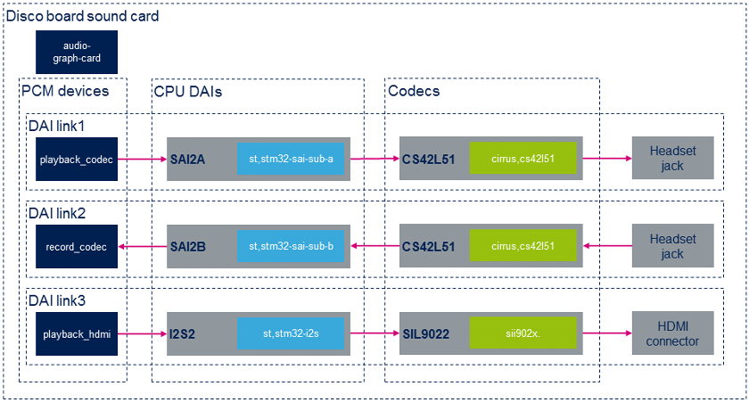
Static configuration
下面摘录自STM32MP15 DISCO主板设备树。 此处仅显示与声卡关联的节点以及最相关的属性。例如,使用green字体强调链接节点以形成第一DAI链接的属性。
/ {
/ * SOUNDCARD */
sound {
compatible = "audio-graph-card";
label = "STM32MP1-DK"; /* Sound card identified as STM32MP1DK in ALSA */
routing =
"Playback" , "MCLK",
"Capture" , "MCLK",
"MICL" , "Mic Bias";
dais = <&sai2a_port &sai2b_port &i2s2_port>;
status = "okay";
};
};
/ * CODECS */
&i2c1 {
cs42l51: cs42l51@4a {
compatible = "cirrus,cs42l51";
...
clocks = <&sai2a>;
clock-names = "MCLK";
cs42l51_port: port {
#address-cells = <1>;
#size-cells = <0>;
cs42l51_tx_endpoint: endpoint@0 {
reg = <0>;
remote-endpoint = <&sai2a_endpoint;
frame-master; /* codec is master */
bitclock-master;
};
cs42l51_rx_endpoint: endpoint@1 {
reg = <1>;
remote-endpoint = <&sai2b_endpoint>;
frame-master; /* codec is master */
bitclock-master;
};
};
};
hdmi-transmitter@39 {
compatible = "sil,sii9022";
...
ports {
#address-cells = <1>;
#size-cells = <0>;
port@0 {
reg = <0>;
sii9022_in: endpoint {
remote-endpoint = <<dc_ep0_out>;
};
};
port@1 {
reg = <1>;
sii9022_tx_endpoint: endpoint {
remote-endpoint = <&i2s2_endpoint>;
};
};
};
};
};
/* CPU DAIS */
&sai2 {
clocks = <&rcc SAI2>, <&rcc PLL3_Q>, <&rcc PLL3_Q>;
clock-names = "pclk", "x8k", "x11k";
pinctrl-names = "default", "sleep";
pinctrl-0 = <&sai2a_pins_a>, <&sai2b_pins_b>;
pinctrl-1 = <&sai2a_sleep_pins_a>, <&sai2b_sleep_pins_b>;
status = "okay";
sai2a: audio-controller@4400b004 {
compatible = "st,stm32-sai-sub-a";
#clock-cells = <0>;
dma-names = "tx"; /* SAI set as transmitter */
clocks = <&rcc SAI2_K>;
clock-names = "sai_ck";
sai2a_port: port {
sai2a_endpoint: endpoint {
remote-endpoint = <&cs42l51_tx_endpoint>;
format = "i2s";
mclk-fs = <256>;
dai-tdm-slot-num = <2>;
dai-tdm-slot-width = <32>;
};
};
};
sai2b: audio-controller@4400b024 {
dma-names = "rx"; /* SAI set as receiver */
st,sync = <&sai2a 2>; /* SAI2B is slave of SAI2A */
clocks = <&rcc SAI2_K>, <&sai2a>;
clock-names = "sai_ck", "MCLK";
sai2b_port: port {
sai2b_endpoint: endpoint {
remote-endpoint = <&cs42l51_rx_endpoint>;
format = "i2s";
mclk-fs = <256>;
dai-tdm-slot-num = <2>;
dai-tdm-slot-width = <32>;
};
};
};
};
&i2s2 {
clocks = <&rcc SPI2>, <&rcc SPI2_K>, <&rcc PLL3_Q>, <&rcc PLL4_Q>;
clock-names = "pclk", "i2sclk", "x8k", "x11k";
pinctrl-names = "default", "sleep";
pinctrl-0 = <&i2s2_pins_a>;
pinctrl-1 = <&i2s2_pins_sleep_a>;
status = "okay";
i2s2_port: port {
i2s2_endpoint: endpoint {
remote-endpoint = <&sii9022_tx_endpoint>;
format = "i2s";
mclk-fs = <256>;
};
};
};
STMP32MP15 Disco板的特定于卡的alsa-lib配置文件为/usr/share/alsa/cards/STM32MP1DK.conf
Dynamic configuration
下表概述了允许配置STM32MPU DISCO主板声卡的控件。
| audio device | CPU DAI | codec |
|---|---|---|
| playback_codec | no controls available | configure codec output path |
| record_codec | no controls available | configure codec input path |
| playback_hdmi | no controls available | no controls available |
Cirrus cs42l51 output configuration
- 控制命令,用于在cs42l51编解码器上将aif接口配置为耳机输出(AOUTA / B)路径:
amixer -c STM32MP1DK cset name='PCM Playback Switch' 'on','on'
amixer -c STM32MP1DK cset name='PCM Playback Volume' '63','63'
amixer -c STM32MP1DK cset name='Analog Playback Volume' '204','204'
amixer -c STM32MP1DK cset name='PCM channel mixer' 'L R'
Cirrus cs42l51 input configuration
- 控制命令,用于在cs42l51编解码器上将耳机麦克风输入(MICIN1 / AIN3A)配置到aif接口:
amixer -c STM32MP1DK cset name='PGA-ADC Mux Left' '3'
amixer -c STM32MP1DK cset name='Mic Boost Volume' '1','1'
References
- ↑ 1.01.1 Documentation/devicetree/bindings/sound/audio-graph-card.txt| |}} Documentation/devicetree/bindings/sound/audio-graph-card.txt
- ↑ Documentation/devicetree/bindings/graph.txt| |}} Documentation/devicetree/bindings/graph.txt
- ↑ 3.03.13.2 asound.conf
- ↑ Documentation/devicetree/bindings/sound/spdif-transmitter.txt| |}} Documentation/devicetree/bindings/sound/spdif-transmitter.txt
- ↑ Documentation/devicetree/bindings/sound/spdif-receiver.txt| |}} Documentation/devicetree/bindings/sound/spdif-receiver.txt