“Soundcard configuration”的版本间的差异
Zhouyuebiao(讨论 | 贡献) |
Zhouyuebiao(讨论 | 贡献) |
||
| 第1行: | 第1行: | ||
| − | + | == Overview == | |
| + | This article explains how to configure ST audio peripherals, as well as [[:Category:Getting_started_with_STM32MP1_boards|STM32MP1 boards]] external audio components, when they are assigned to the '''Linux® OS'''. In such cases, they are controlled by the ALSA framework. | ||
| − | [[ | + | In the ASoC layer of the [[ALSA_overview|ALSA framework]], audio hardware components are described as [[ALSA_overview#Component_descriptions|CPU DAIs and codec]], which are linked together to create DAI links. A sound card is a software component gathering a set of DAI links. |
| − | [[ | + | |
| − | [[Category:ALSA]] | + | Each of the following STM32 MPU board sections describes one or more sound cards. |
| + | A schematic for each sound card is provided, as well as its means of static and dynamic configuration. | ||
| + | |||
| + | === Sound card schematic === | ||
| + | |||
| + | The sound card schematic gives an overview of the hardware and software components forming the sound card, and their relationships. | ||
| + | |||
| + | The example sound card schematic given below emphasizes the links between the sound card and the device-tree section. | ||
| + | |||
| + | [[File:alsa_soundcard_config_overview.png.png|center|link=]] | ||
| + | |||
| + | === Static configuration === | ||
| + | |||
| + | * Device tree | ||
| + | |||
| + | The device tree allows the description, configuration and connection of the audio hardware components to define the sound card. The user has to follow the audio graph card bindings<ref name="Audio graph card bindings">{{CodeSource | Linux kernel | Documentation/devicetree/bindings/sound/audio-graph-card.txt}}</ref> to configure the sound card and device graph bindings<ref name="Device graph bindings">{{CodeSource | Linux kernel | Documentation/devicetree/bindings/graph.txt}}</ref> to connect audio components. The user must also refer to the audio component (codec and CPU DAI) bindings to configure these components properly. The bindings of the audio components can be found in device-tree samples in following sections and in the [[Soundcard configuration#References|References chapter]]. | ||
| + | |||
| + | The STMicroelectronics configuration tool [[STM32CubeMX]], allows the generation of CPU DAI device tree nodes. {{Warning|STM32CubeMX does not allow configuration of sound card and codec nodes, which are board dependent. The sound card node and the codec nodes have to be filled manually through user sections.}} | ||
| + | |||
| + | * asound.conf <ref name="asound.conf">[https://www.alsa-project.org/main/index.php/Asoundrc asound.conf]</ref> | ||
| + | |||
| + | The optional asound.conf<ref name="asound.conf"></ref> system-global custom settings file, provides extra functionalities, such as routing and audio sample conversion. It can be found in the /etc directory. | ||
| + | |||
| + | * Sound card configuration files <ref name="asound.conf"></ref> | ||
| + | |||
| + | The alsa-lib layer provides card configuration files in /usr/share/alsa/cards directory. These files allow to map ALSA hardware devices on standard devices, such as "front", "hdmi" or "iec958" devices. The label defined in sound card device tree node defines the name of the card. The card configuration is retrieved from this card name, according to /usr/share/alsa/cards/aliases.conf mapping. | ||
| + | |||
| + | === Dynamic configuration === | ||
| + | |||
| + | The codecs and CPU DAI drivers also provide ALSA controls, allowing dynamic configuration of the sound card. The controls | ||
| + | can be changed at runtime through the [[ALSA_overview#How_to_use|amixer]] utility to modify certain settings in the audio path. For instance, such controls can be used to modify the audio volume or the mute state of a block in the codec. | ||
| + | |||
| + | A customized configuration of these controls can be saved in the asound.state configuration file using the [[ALSA_overview#How_to_use|alsactl]] utility. This configuration can be restored at boot time through [[ALSA_overview#How_to_use|alsactl]]. STM32MPU sound cards come with a dedicated asound.state configuration file providing relevant control settings. | ||
| + | |||
| + | == STM32MP15 evaluation board sound card configuration == | ||
| + | |||
| + | === Sound card overview === | ||
| + | |||
| + | {{ | ||
| + | ImageMap| | ||
| + | Image:mp15_ev_main_soundcard.png {{!}} frame {{!}} center{{!}} STM32MP15 Evaluation board sound card | ||
| + | rect 187 154 257 202 [[SAI internal peripheral]] | ||
| + | rect 187 252 257 300 [[SAI internal peripheral]] | ||
| + | rect 187 350 257 398 [[SAI internal peripheral]] | ||
| + | rect 187 448 257 496 [[SPDIFRX internal peripheral]] | ||
| + | rect 265 160 386 196 [[SAI Linux driver]] | ||
| + | rect 265 258 386 294 [[SAI Linux driver]] | ||
| + | rect 265 356 386 392 [[SAI Linux driver]] | ||
| + | rect 265 454 386 490 [[SPDIFRX Linux driver]] | ||
| + | rect 448 153 518 201 [[Audio_codecs_hardware_components]] | ||
| + | rect 448 251 518 299 [[Audio_codecs_hardware_components]] | ||
| + | rect 187 546 247 594 [[DFSDM internal peripheral]] | ||
| + | rect 187 742 247 790 [[DFSDM internal peripheral]] | ||
| + | rect 187 840 247 888 [[DFSDM internal peripheral]] | ||
| + | rect 187 644 247 692 [[DFSDM internal peripheral]] | ||
| + | rect 252 552 384 588 [[DFSDM Linux driver]] | ||
| + | rect 252 650 384 686 [[DFSDM Linux driver]] | ||
| + | rect 252 748 384 784 [[DFSDM Linux driver]] | ||
| + | rect 252 847 384 883 [[DFSDM Linux driver]] | ||
| + | rect 448 545 523 593 [[Audio_codecs_hardware_components#ST_MP34DT01-M]] | ||
| + | rect 448 644 523 692 [[Audio_codecs_hardware_components#ST_MP34DT01-M]] | ||
| + | rect 448 741 523 789 [[Audio_codecs_hardware_components#ST_MP34DT01-M]] | ||
| + | rect 448 839 523 887 [[Audio_codecs_hardware_components#ST_MP34DT01-M]] | ||
| + | }} | ||
| + | |||
| + | === Static configuration === | ||
| + | |||
| + | The extract below is from the STM32MP15 evaluation board device tree. Only the nodes associated to the sound card, and the most relevant properties are shown here. For example, the properties linking nodes to form the first DAI link are emphasized with {{green|green}} font. | ||
| + | |||
| + | / * '''SOUNDCARD''' */ | ||
| + | sound { | ||
| + | compatible = "audio-graph-card<ref name="Audio graph card bindings" />"; | ||
| + | label = "STM32MP1-EV"; {{highlight|/* Sound card identified as STM32MP1EV in ALSA */}} | ||
| + | routing = | ||
| + | "AIF1CLK" , "MCLK1", | ||
| + | "AIF2CLK" , "MCLK1", | ||
| + | "IN1LN" , "MICBIAS2", | ||
| + | "DMIC2DAT" , "MICBIAS1", | ||
| + | "DMIC1DAT" , "MICBIAS1"; | ||
| + | dais = <&sai2a_port &sai2b_port &sai4a_port &spdifrx_port | ||
| + | &dfsdm0_port &dfsdm1_port &dfsdm2_port &dfsdm3_port>; | ||
| + | }; | ||
| + | |||
| + | / * '''CODECS''' */ | ||
| + | spdif_out: spdif-out { | ||
| + | compatible = "linux,spdif-dit<ref name="spdif-dit">{{CodeSource | Linux kernel | Documentation/devicetree/bindings/sound/spdif-transmitter.txt}}</ref>"; | ||
| + | |||
| + | spdif_out_port: port@0 { | ||
| + | spdif_out_endpoint: endpoint { | ||
| + | remote-endpoint = <&sai4a_endpoint>; | ||
| + | }; | ||
| + | }; | ||
| + | }; | ||
| + | |||
| + | spdif_in: spdif-in { | ||
| + | compatible = "linux,spdif-dir<ref name="spdif-dir">{{CodeSource | Linux kernel | Documentation/devicetree/bindings/sound/spdif-receiver.txt}}</ref>"; | ||
| + | spdif_in_port: port@0 { | ||
| + | spdif_in_endpoint: endpoint { | ||
| + | remote-endpoint = <&spdifrx_endpoint>; | ||
| + | }; | ||
| + | }; | ||
| + | }; | ||
| + | |||
| + | dmic0: dmic@0 { | ||
| + | compatible = "[[Audio_codecs_hardware_components#ST_MP34DT01-M|dmic-codec]]"; | ||
| + | port { | ||
| + | dmic0_endpoint: endpoint { | ||
| + | remote-endpoint = <&dfsdm_endpoint0>; | ||
| + | }; | ||
| + | }; | ||
| + | }; | ||
| + | |||
| + | dmic1: dmic@1 { | ||
| + | compatible = "[[Audio_codecs_hardware_components#ST_MP34DT01-M|dmic-codec]]"; | ||
| + | port { | ||
| + | dmic1_endpoint: endpoint { | ||
| + | remote-endpoint = <&dfsdm_endpoint1>; | ||
| + | }; | ||
| + | }; | ||
| + | }; | ||
| + | |||
| + | dmic2: dmic@2 { | ||
| + | compatible = "[[Audio_codecs_hardware_components#ST_MP34DT01-M|dmic-codec]]"; | ||
| + | port { | ||
| + | dmic2_endpoint: endpoint { | ||
| + | remote-endpoint = <&dfsdm_endpoint2>; | ||
| + | }; | ||
| + | }; | ||
| + | }; | ||
| + | |||
| + | dmic3: dmic@3 { | ||
| + | compatible = "[[Audio_codecs_hardware_components#ST_MP34DT01-M|dmic-codec]]"; | ||
| + | port { | ||
| + | dmic3_endpoint: endpoint { | ||
| + | remote-endpoint = <&dfsdm_endpoint3>; | ||
| + | }; | ||
| + | }; | ||
| + | }; | ||
| + | }; | ||
| + | |||
| + | &i2c2 { | ||
| + | wm8994: wm8994@1b { | ||
| + | compatible = "[[Audio_codecs_hardware_components#Wolfson_wm8994|wlf,wm8994]]"; | ||
| + | ... | ||
| + | clocks = <&sai2a>; | ||
| + | clock-names = "MCLK1"; | ||
| + | |||
| + | ports { | ||
| + | #address-cells = <1>; | ||
| + | #size-cells = <0>; | ||
| + | |||
| + | <span id="dt_mp15_ev_main_8994_tx_port">{{green|wm8994_tx_port}}</span>: port@0 { | ||
| + | wm8994_tx_endpoint: endpoint { | ||
| + | remote-endpoint = <&[[#dt_mp15_ev_main_sai2a_ep|{{green|sai2a_endpoint}}]]>; | ||
| + | }; | ||
| + | }; | ||
| + | |||
| + | wm8994_rx_port: port@1 { | ||
| + | wm8994_rx_endpoint: endpoint { | ||
| + | remote-endpoint = <&sai2b_endpoint>; | ||
| + | }; | ||
| + | }; | ||
| + | }; | ||
| + | }; | ||
| + | }; | ||
| + | |||
| + | /* '''CPU DAIS''' */ | ||
| + | &sai2 { | ||
| + | clocks = <&rcc SAI2>, <&rcc PLL3_Q>, <&rcc PLL4_Q>; | ||
| + | pinctrl-names = "default", "sleep"; | ||
| + | pinctrl-0 = <&sai2a_pins_a>, <&sai2b_pins_a>; | ||
| + | pinctrl-1 = <&sai2a_sleep_pins_a>, <&sai2b_sleep_pins_a>; | ||
| + | clock-names = "pclk", "x8k", "x11k"; | ||
| + | |||
| + | sai2a: audio-controller@4400b004 { | ||
| + | compatible = "[[SAI device tree configuration|st,stm32-sai-sub-a]]"; | ||
| + | dma-names = "{{highlight|tx}}"; {{highlight|/* SAI set as transmitter */}} | ||
| + | clocks = <&rcc SAI2_K>; | ||
| + | clock-names = "sai_ck"; | ||
| + | |||
| + | <span id="dt_mp15_ev_main_sai2a_port">{{green|sai2a_port}}</span>: port@0 { | ||
| + | <span id="dt_mp15_ev_main_sai2a_ep">{{green|sai2a_endpoint}}: endpoint { | ||
| + | remote-endpoint = <&[[#dt_mp15_ev_main_8994_tx_port|{{green|wm8994_tx_endpoint}}]]>; | ||
| + | format = "i2s"; | ||
| + | mclk-fs = {{highlight|<256>}}; {{highlight|/* SAI is master clock provider */}} | ||
| + | }; | ||
| + | }; | ||
| + | }; | ||
| + | |||
| + | sai2b: audio-controller@4400b024 { | ||
| + | compatible = "[[SAI device tree configuration|st,stm32-sai-sub-b]]"; | ||
| + | dma-names = "{{highlight|rx}}"; {{highlight|/* SAI set as receiver */}} | ||
| + | clocks = <&rcc SAI2_K>, <&sai2a>; | ||
| + | clock-names = "sai_ck", "MCLK"; | ||
| + | |||
| + | sai2b_port: port@0 { | ||
| + | sai2b_endpoint: endpoint { | ||
| + | remote-endpoint = <&wm8994_rx_endpoint>; | ||
| + | format = "i2s"; | ||
| + | mclk-fs = {{highlight|<256>}}; {{highlight|/* SAI is master clock provider */}} | ||
| + | }; | ||
| + | }; | ||
| + | }; | ||
| + | }; | ||
| + | |||
| + | &sai4 { | ||
| + | clocks = <&rcc SAI4>, <&rcc PLL3_Q>, <&rcc PLL4_Q>; | ||
| + | clock-names = "pclk", "x8k", "x11k"; | ||
| + | |||
| + | sai4a: audio-controller@50027004 { | ||
| + | compatible = "[[SAI device tree configuration|st,stm32-sai-sub-a]]"; | ||
| + | dma-names = "tx"; | ||
| + | {{highlight|st,iec60958}}; {{highlight|/* SAI configured for S/PDIF protocol*/}} | ||
| + | pinctrl-names = "default", "sleep"; | ||
| + | pinctrl-0 = <&sai4a_pins_a>; | ||
| + | pinctrl-1 = <&sai4a_sleep_pins_a>; | ||
| + | clocks = <&rcc SAI4_K>; | ||
| + | clock-names = "sai_ck"; | ||
| + | |||
| + | sai4a_port: port@0 { | ||
| + | sai4a_endpoint: endpoint { | ||
| + | remote-endpoint = <&spdif_out_endpoint>; | ||
| + | }; | ||
| + | }; | ||
| + | }; | ||
| + | }; | ||
| + | |||
| + | &spdifrx { | ||
| + | compatible = "[[SPDIFRX device tree configuration|st,stm32h7-spdifrx]]"; | ||
| + | pinctrl-names = "default", "sleep"; | ||
| + | pinctrl-0 = <&spdifrx_pins_a>; | ||
| + | pinctrl-1 = <&spdifrx_sleep_pins_a>; | ||
| + | |||
| + | spdifrx_port: port@0 { | ||
| + | spdifrx_endpoint: endpoint { | ||
| + | remote-endpoint = <&spdif_in_endpoint>; | ||
| + | }; | ||
| + | }; | ||
| + | |||
| + | &dfsdm { | ||
| + | compatible = "st,stm32mp1-dfsdm"; | ||
| + | pinctrl-names = "default", "sleep"; | ||
| + | pinctrl-0 = <&dfsdm_clkout_pins_a | ||
| + | &dfsdm_data1_pins_a &dfsdm_data3_pins_a>; | ||
| + | pinctrl-1 = <&dfsdm_clkout_sleep_pins_a | ||
| + | &dfsdm_data1_sleep_pins_a &dfsdm_data3_sleep_pins_a>; | ||
| + | spi-max-frequency = <2048000>; | ||
| + | |||
| + | clocks = <&rcc DFSDM_K>, <&rcc ADFSDM_K>; | ||
| + | clock-names = "dfsdm", "audio"; | ||
| + | |||
| + | dfsdm0: filter@0 { | ||
| + | compatible = "[[DFSDM device tree configuration|st,stm32-dfsdm-dmic]]"; | ||
| + | st,adc-channels = <{{highlight|3>}}; {{highlight|/* Use channel 3, shared with mic U3 */}} | ||
| + | st,adc-channel-names = "{{highlight|dmic_u1}}"; {{highlight|/* Left mic U1 associated with Right mic U3, for stereo */}} | ||
| + | st,adc-channel-types = "SPI_R"; {{highlight|/* Rising edge for left channel */}} | ||
| + | st,adc-channel-clk-src = "CLKOUT"; {{highlight|/* CKOUT clocks the microphones */}} | ||
| + | st,filter-order = <3>; | ||
| + | |||
| + | asoc_pdm0: dfsdm-dai { | ||
| + | compatible = "[[DFSDM device tree configuration|st,stm32h7-dfsdm-dai]]"; | ||
| + | #sound-dai-cells = <0>; | ||
| + | io-channels = <&dfsdm0 0>; | ||
| + | cpu_port0: port { | ||
| + | dfsdm_endpoint0: endpoint { | ||
| + | remote-endpoint = <&dmic0_endpoint>; | ||
| + | }; | ||
| + | }; | ||
| + | }; | ||
| + | }; | ||
| + | |||
| + | dfsdm1: filter@1 { | ||
| + | compatible = "[[DFSDM device tree configuration|st,stm32-dfsdm-dmic]]"; | ||
| + | st,adc-channels = <1>; | ||
| + | st,adc-channel-names = "dmic_u2"; | ||
| + | st,adc-channel-types = "SPI_F"; | ||
| + | st,adc-channel-clk-src = "CLKOUT"; | ||
| + | st,filter-order = <3>; | ||
| + | |||
| + | asoc_pdm1: dfsdm-dai { | ||
| + | compatible = "[[DFSDM device tree configuration|st,stm32h7-dfsdm-dai]]"; | ||
| + | #sound-dai-cells = <0>; | ||
| + | io-channels = <&dfsdm1 0>; | ||
| + | cpu_port1: port { | ||
| + | dfsdm_endpoint1: endpoint { | ||
| + | remote-endpoint = <&dmic1_endpoint>; | ||
| + | }; | ||
| + | }; | ||
| + | }; | ||
| + | }; | ||
| + | |||
| + | dfsdm2: filter@2 { | ||
| + | compatible = "[[DFSDM device tree configuration|st,stm32-dfsdm-dmic]]"; | ||
| + | st,adc-channels = <{{highlight|3}}>; {{highlight|/* Use channel 3, shared with mic U1 */}} | ||
| + | st,adc-channel-names = "{{highlight|dmic_u3}}"; {{highlight|/* Right mic U3 associated with Left mic U1, for stereo */}} | ||
| + | st,adc-channel-types = "SPI_F"; {{highlight|/* Falling edge for Right channel */}} | ||
| + | st,adc-channel-clk-src = "CLKOUT"; | ||
| + | st,filter-order = <3>; | ||
| + | |||
| + | asoc_pdm2: dfsdm-dai { | ||
| + | compatible = "[[DFSDM device tree configuration|st,stm32h7-dfsdm-dai]]"; | ||
| + | #sound-dai-cells = <0>; | ||
| + | io-channels = <&dfsdm2 0>; | ||
| + | cpu_port2: port { | ||
| + | dfsdm_endpoint2: endpoint { | ||
| + | remote-endpoint = <&dmic2_endpoint>; | ||
| + | }; | ||
| + | }; | ||
| + | }; | ||
| + | }; | ||
| + | |||
| + | dfsdm3: filter@3 { | ||
| + | compatible = "[[DFSDM device tree configuration|st,stm32-dfsdm-dmic]]"; | ||
| + | st,adc-channels = <1>; | ||
| + | st,adc-channel-names = "dmic_u4"; | ||
| + | st,adc-channel-types = "SPI_R"; | ||
| + | st,adc-channel-clk-src = "CLKOUT"; | ||
| + | st,filter-order = <3>; | ||
| + | |||
| + | asoc_pdm3: dfsdm-dai { | ||
| + | compatible = "[[DFSDM device tree configuration|st,stm32h7-dfsdm-dai]]"; | ||
| + | #sound-dai-cells = <0>; | ||
| + | io-channels = <&dfsdm3 0>; | ||
| + | cpu_port3: port { | ||
| + | dfsdm_endpoint3: endpoint { | ||
| + | remote-endpoint = <&dmic3_endpoint>; | ||
| + | }; | ||
| + | }; | ||
| + | }; | ||
| + | }; | ||
| + | }; | ||
| + | |||
| + | The card-specific alsa-lib configuration file for STMP32MP15 Evaluation board is /usr/share/alsa/cards/STM32MP1EV.conf. | ||
| + | |||
| + | === Dynamic configuration === | ||
| + | |||
| + | The table below gives an overview of the controls allowing configuration of the STM32MPU evaluation board "sound" sound card. | ||
| + | |||
| + | {| class="st-table" | ||
| + | ! audio device | ||
| + | ! CPU DAI | ||
| + | ! codec | ||
| + | |- | ||
| + | | playback_codec | ||
| + | | no controls available | ||
| + | | [[#Wolfson wm8994 output configuration|configure codec output path]] | ||
| + | |- | ||
| + | | record_codec | ||
| + | | no controls available | ||
| + | | [[#Wolfson wm8994 input configuration|configure codec input path]] | ||
| + | |- | ||
| + | | playback_spdif | ||
| + | | [[ALSA_overview#IEC_controls|configure iec958]] | ||
| + | | no controls available | ||
| + | |- | ||
| + | | record_spdif | ||
| + | | [[#SPDFIRX input configuration|configure SPDFIRX input path]] | ||
| + | | no controls available | ||
| + | |} | ||
| + | |||
| + | ==== Wolfson wm8994 output configuration ==== | ||
| + | |||
| + | :Control commands to configure aif1 interface to headset output (HPOUT1L/R) path, on wm8994 codec: | ||
| + | |||
| + | <div style="margin-left: 2em;"> | ||
| + | amixer -c STM32MP1EV cset name='AIF1DAC1 Volume' '96' '96' | ||
| + | amixer -c STM32MP1EV cset name='Headphone Volume' '63' '63' | ||
| + | amixer -c STM32MP1EV cset name='DAC1 Volume' '50' '50' | ||
| + | amixer -c STM32MP1EV cset name='DAC1L Mixer AIF1.1 Switch' 'on' | ||
| + | amixer -c STM32MP1EV cset name='DAC1R Mixer AIF1.1 Switch' 'on' | ||
| + | amixer -c STM32MP1EV cset name='DAC1 Switch' 'on' 'on' | ||
| + | amixer -c STM32MP1EV cset name='Left Output Mixer DAC Switch' 'on' | ||
| + | amixer -c STM32MP1EV cset name='Right Output Mixer DAC Switch' 'on' | ||
| + | amixer -c STM32MP1EV cset name='Headphone Switch' 'on' 'on' | ||
| + | </div> | ||
| + | |||
| + | :Control commands to configure aif1 interface to speaker output (SPKOUTL/RP) path, on wm8994 codec: | ||
| + | |||
| + | <div style="margin-left: 2em;"> | ||
| + | amixer -c STM32MP1EV cset name='AIF1DAC1 Volume' '96' '96' | ||
| + | amixer -c STM32MP1EV cset name='DAC1L Mixer AIF1.1 Switch' 'on' | ||
| + | amixer -c STM32MP1EV cset name='DAC1R Mixer AIF1.1 Switch' 'on' | ||
| + | amixer -c STM32MP1EV cset name='DAC1 Switch' 'on','on' | ||
| + | amixer -c STM32MP1EV cset name='DAC1 Volume' '96','96' | ||
| + | amixer -c STM32MP1EV cset name='SPKL DAC1 Volume' '50' '50' | ||
| + | amixer -c STM32MP1EV cset name='SPKR DAC1 Volume' '50' '50' | ||
| + | amixer -c STM32MP1EV cset name='SPKL DAC1 Switch' 'on' | ||
| + | amixer -c STM32MP1EV cset name='SPKR DAC1 Switch' 'on' | ||
| + | amixer -c STM32MP1EV cset name='SPKL Output Switch' 'on' | ||
| + | amixer -c STM32MP1EV cset name='SPKR Output Switch' 'on' | ||
| + | amixer -c STM32MP1EV cset name='Speaker Mode' 'Class AB' | ||
| + | amixer -c STM32MP1EV cset name='Speaker Volume' '50' '50' | ||
| + | amixer -c STM32MP1EV cset name='Speaker Mixer Volume' 3 | ||
| + | amixer -c STM32MP1EV cset name='Speaker Reference' 0 | ||
| + | amixer -c STM32MP1EV cset name='Speaker Switch' 'on' | ||
| + | </div> | ||
| + | |||
| + | ==== Wolfson wm8994 input configuration ==== | ||
| + | |||
| + | :Control commands to configure headset microphone input (IN1LN) to aif2 interface, on wm8994 codec: | ||
| + | |||
| + | <div style="margin-left: 2em;"> | ||
| + | amixer -c STM32MP1EV cset name='IN1L PGA IN1LN Switch' 'on' | ||
| + | amixer -c STM32MP1EV cset name='IN1L PGA IN1LP Switch' 'off' | ||
| + | amixer -c STM32MP1EV cset name='IN1L Volume' '25' | ||
| + | amixer -c STM32MP1EV cset name='IN1L Switch' 'on' | ||
| + | amixer -c STM32MP1EV cset name='MIXINL IN1L Switch' 'on' | ||
| + | amixer -c STM32MP1EV cset name='MIXINL IN1L Volume' '1' | ||
| + | amixer -c STM32MP1EV cset name='MIXINL IN1LP Volume' '0' | ||
| + | amixer -c STM32MP1EV cset name='AIF1ADCL Source' 'Left' | ||
| + | amixer -c STM32MP1EV cset name='ADCL Mux' 'ADC' | ||
| + | amixer -c STM32MP1EV cset name='DAC2 Left Sidetone Volume' '12' | ||
| + | amixer -c STM32MP1EV cset name='DAC2 Right Sidetone Volume' '12' | ||
| + | amixer -c STM32MP1EV cset name='AIF2DAC2L Mixer Left Sidetone Switch' 'on' | ||
| + | amixer -c STM32MP1EV cset name='AIF2DAC2R Mixer Right Sidetone Switch' 'on' | ||
| + | amixer -c STM32MP1EV cset name='DAC2 Volume' '96' '96' | ||
| + | amixer -c STM32MP1EV cset name='DAC2 Switch' 'on' 'on' | ||
| + | amixer -c STM32MP1EV cset name='AIF2ADC Volume' '96' '96' | ||
| + | amixer -c STM32MP1EV cset name='AIF2ADC Mux' 'AIF2ADCDAT' | ||
| + | amixer -c STM32MP1EV cset name='AIF2 Boost Volume' '1' | ||
| + | amixer -c STM32MP1EV cset name='ADC OSR' 'Low Power' | ||
| + | </div> | ||
| + | |||
| + | ==== SPDFIRX input configuration ==== | ||
| + | |||
| + | :Control commands to configure rx1 input path on SPDFIRX: | ||
| + | |||
| + | <div style="margin-left: 2em;"> | ||
| + | amixer -c STM32MP1EV cset name='SPDIFRX input' 1 | ||
| + | </div> | ||
| + | |||
| + | == STM32MP15 disco board sound card configuration == | ||
| + | |||
| + | === Sound card overview === | ||
| + | |||
| + | {{ | ||
| + | ImageMap| | ||
| + | Image:mp15_dk_main_soundcard.png {{!}} frame {{!}} center{{!}} STM32MP15 Disco board sound card | ||
| + | rect 187 154 256 202 [[SAI internal peripheral]] | ||
| + | rect 187 252 256 300 [[SAI internal peripheral]] | ||
| + | rect 187 350 256 398 [[SPI internal peripheral]] | ||
| + | rect 265 160 386 195 [[SAI Linux driver]] | ||
| + | rect 265 258 385 293 [[SAI Linux driver]] | ||
| + | rect 265 356 385 391 [[I2S Linux driver]] | ||
| + | rect 448 153 517 201 [[Audio_codecs_hardware_components]] | ||
| + | rect 448 251 517 299 [[Audio_codecs_hardware_components]] | ||
| + | rect 448 350 517 398 [[Audio_codecs_hardware_components]] | ||
| + | }} | ||
| + | |||
| + | === Static configuration === | ||
| + | The extract below is from the STM32MP15 disco board device tree. Only the nodes associated to the sound card, and the most relevant properties are shown here. As an example, the properties linking nodes to form the first DAI link are emphasized with {{green|green}} font. | ||
| + | |||
| + | / { | ||
| + | / * '''SOUNDCARD''' */ | ||
| + | sound { | ||
| + | compatible = "audio-graph-card"; | ||
| + | label = "STM32MP1-DK"; {{highlight|/* Sound card identified as STM32MP1DK in ALSA */}} | ||
| + | routing = | ||
| + | "Playback" , "MCLK", | ||
| + | "Capture" , "MCLK", | ||
| + | "MICL" , "Mic Bias"; | ||
| + | dais = <&[[#dt_mp15_dk_main_sai2a_port|{{green|sai2a_port}}]] &sai2b_port &i2s2_port>; | ||
| + | status = "okay"; | ||
| + | }; | ||
| + | }; | ||
| + | |||
| + | / * '''CODECS''' */ | ||
| + | &i2c1 { | ||
| + | cs42l51: cs42l51@4a { | ||
| + | compatible = "[[Audio_codecs_hardware_components#Cirrus_cs42l51|cirrus,cs42l51]]"; | ||
| + | ... | ||
| + | |||
| + | clocks = <&sai2a>; | ||
| + | clock-names = "MCLK"; | ||
| + | |||
| + | cs42l51_port: port { | ||
| + | #address-cells = <1>; | ||
| + | #size-cells = <0>; | ||
| + | |||
| + | <span id="dt_mp15_dk_main_cs42l51_tx_endpoint">{{green|cs42l51_tx_endpoint}}</span>: endpoint@0 { | ||
| + | reg = <0>; | ||
| + | remote-endpoint = <&[[#dt_mp15_dk_main_sai2a_ep|{{green|sai2a_endpoint}}]]; | ||
| + | frame-master; {{highlight|/* codec is master */}} | ||
| + | bitclock-master; | ||
| + | }; | ||
| + | |||
| + | cs42l51_rx_endpoint: endpoint@1 { | ||
| + | reg = <1>; | ||
| + | remote-endpoint = <&sai2b_endpoint>; | ||
| + | frame-master; {{highlight|/* codec is master */}} | ||
| + | bitclock-master; | ||
| + | }; | ||
| + | }; | ||
| + | }; | ||
| + | |||
| + | hdmi-transmitter@39 { | ||
| + | compatible = "[[Audio_codecs_hardware_components#Silab_sil9022|sil,sii9022]]"; | ||
| + | ... | ||
| + | |||
| + | ports { | ||
| + | #address-cells = <1>; | ||
| + | #size-cells = <0>; | ||
| + | |||
| + | port@0 { | ||
| + | reg = <0>; | ||
| + | sii9022_in: endpoint { | ||
| + | remote-endpoint = <<dc_ep0_out>; | ||
| + | }; | ||
| + | }; | ||
| + | |||
| + | port@1 { | ||
| + | reg = <1>; | ||
| + | sii9022_tx_endpoint: endpoint { | ||
| + | remote-endpoint = <&i2s2_endpoint>; | ||
| + | }; | ||
| + | }; | ||
| + | }; | ||
| + | }; | ||
| + | }; | ||
| + | |||
| + | |||
| + | |||
| + | /* '''CPU DAIS''' */ | ||
| + | &sai2 { | ||
| + | clocks = <&rcc SAI2>, <&rcc PLL3_Q>, <&rcc PLL3_Q>; | ||
| + | clock-names = "pclk", "x8k", "x11k"; | ||
| + | pinctrl-names = "default", "sleep"; | ||
| + | pinctrl-0 = <&sai2a_pins_a>, <&sai2b_pins_b>; | ||
| + | pinctrl-1 = <&sai2a_sleep_pins_a>, <&sai2b_sleep_pins_b>; | ||
| + | status = "okay"; | ||
| + | |||
| + | sai2a: audio-controller@4400b004 { | ||
| + | compatible = "[[SAI device tree configuration|st,stm32-sai-sub-a]]"; | ||
| + | #clock-cells = <0>; | ||
| + | dma-names = "{{highlight|tx}}"; {{highlight|/* SAI set as transmitter */}} | ||
| + | clocks = <&rcc SAI2_K>; | ||
| + | clock-names = "sai_ck"; | ||
| + | |||
| + | <span id="dt_mp15_dk_main_sai2a_port">{{green|sai2a_port}}</span>: port { | ||
| + | <span id="dt_mp15_dk_main_sai2a_ep">{{green|sai2a_endpoint}}: endpoint { | ||
| + | remote-endpoint = <&[[#dt_mp15_dk_main_cs42l51_tx_endpoint|{{green|cs42l51_tx_endpoint}}]]>; | ||
| + | format = "i2s"; | ||
| + | mclk-fs = <256>; | ||
| + | dai-tdm-slot-num = <2>; | ||
| + | dai-tdm-slot-width = <32>; | ||
| + | }; | ||
| + | }; | ||
| + | }; | ||
| + | |||
| + | sai2b: audio-controller@4400b024 { | ||
| + | dma-names = "{{highlight|rx}}"; {{highlight|/* SAI set as receiver */}} | ||
| + | st,sync = {{highlight|<&sai2a 2>}}; {{highlight|/* SAI2B is slave of SAI2A */}} | ||
| + | clocks = <&rcc SAI2_K>, <&sai2a>; | ||
| + | clock-names = "sai_ck", "MCLK"; | ||
| + | |||
| + | sai2b_port: port { | ||
| + | sai2b_endpoint: endpoint { | ||
| + | remote-endpoint = <&cs42l51_rx_endpoint>; | ||
| + | format = "i2s"; | ||
| + | mclk-fs = <256>; | ||
| + | dai-tdm-slot-num = <2>; | ||
| + | dai-tdm-slot-width = <32>; | ||
| + | }; | ||
| + | }; | ||
| + | }; | ||
| + | }; | ||
| + | |||
| + | &i2s2 { | ||
| + | clocks = <&rcc SPI2>, <&rcc SPI2_K>, <&rcc PLL3_Q>, <&rcc PLL4_Q>; | ||
| + | clock-names = "pclk", "i2sclk", "x8k", "x11k"; | ||
| + | pinctrl-names = "default", "sleep"; | ||
| + | pinctrl-0 = <&i2s2_pins_a>; | ||
| + | pinctrl-1 = <&i2s2_pins_sleep_a>; | ||
| + | status = "okay"; | ||
| + | |||
| + | i2s2_port: port { | ||
| + | i2s2_endpoint: endpoint { | ||
| + | remote-endpoint = <&sii9022_tx_endpoint>; | ||
| + | format = "i2s"; | ||
| + | mclk-fs = <256>; | ||
| + | }; | ||
| + | }; | ||
| + | }; | ||
| + | |||
| + | The card-specific alsa-lib configuration file for STMP32MP15 Disco board is /usr/share/alsa/cards/STM32MP1DK.conf. | ||
| + | |||
| + | === Dynamic configuration === | ||
| + | |||
| + | The table below gives an overview of the controls allowing the configuration of the STM32MPU disco board sound card. | ||
| + | |||
| + | {| class="st-table" | ||
| + | ! audio device | ||
| + | ! CPU DAI | ||
| + | ! codec | ||
| + | |- | ||
| + | | playback_codec | ||
| + | | no controls available | ||
| + | | [[#Cirrus cs42l51 output configuration|configure codec output path]] | ||
| + | |- | ||
| + | | record_codec | ||
| + | | no controls available | ||
| + | | [[#Cirrus cs42l51 input configuration|configure codec input path]] | ||
| + | |- | ||
| + | | playback_hdmi | ||
| + | | no controls available | ||
| + | | no controls available | ||
| + | |} | ||
| + | |||
| + | ==== Cirrus cs42l51 output configuration ==== | ||
| + | |||
| + | :Control commands to configure the aif interface to headset output (AOUTA/B) path, on the cs42l51 codec: | ||
| + | |||
| + | <div style="margin-left: 2em;"> | ||
| + | amixer -c STM32MP1DK cset name='PCM Playback Switch' 'on','on' | ||
| + | amixer -c STM32MP1DK cset name='PCM Playback Volume' '63','63' | ||
| + | amixer -c STM32MP1DK cset name='Analog Playback Volume' '204','204' | ||
| + | amixer -c STM32MP1DK cset name='PCM channel mixer' 'L R' | ||
| + | </div> | ||
| + | |||
| + | ==== Cirrus cs42l51 input configuration ==== | ||
| + | |||
| + | :Control commands to configure headset microphone input (MICIN1/AIN3A) to the aif interface, on the cs42l51 codec: | ||
| + | |||
| + | <div style="margin-left: 2em;"> | ||
| + | amixer -c STM32MP1DK cset name='PGA-ADC Mux Left' '3' | ||
| + | amixer -c STM32MP1DK cset name='Mic Boost Volume' '1','1' | ||
| + | </div> | ||
| + | |||
| + | == References == | ||
| + | <references /> | ||
| + | |||
| + | <noinclude> | ||
| + | {{PublicationRequestId | 9884 |2018-12-11 | PhilipS}} | ||
| + | [[Category:ALSA]] | ||
| + | [[Category:Device tree configuration]] | ||
| + | </noinclude> | ||
2020年5月6日 (三) 22:13的版本
目录
Overview
This article explains how to configure ST audio peripherals, as well as STM32MP1 boards external audio components, when they are assigned to the Linux® OS. In such cases, they are controlled by the ALSA framework.
In the ASoC layer of the ALSA framework, audio hardware components are described as CPU DAIs and codec, which are linked together to create DAI links. A sound card is a software component gathering a set of DAI links.
Each of the following STM32 MPU board sections describes one or more sound cards. A schematic for each sound card is provided, as well as its means of static and dynamic configuration.
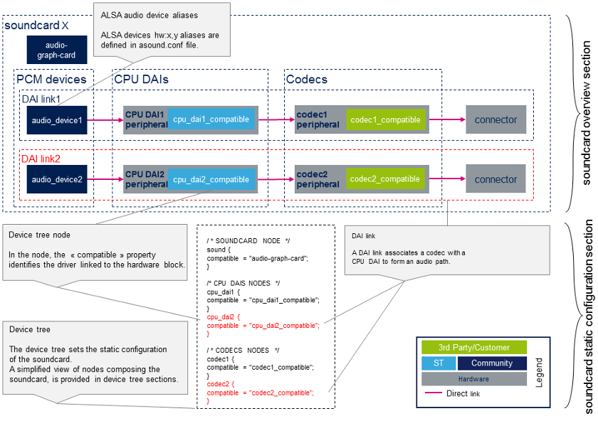
Sound card schematic
The sound card schematic gives an overview of the hardware and software components forming the sound card, and their relationships.
The example sound card schematic given below emphasizes the links between the sound card and the device-tree section.
Static configuration
- Device tree
The device tree allows the description, configuration and connection of the audio hardware components to define the sound card. The user has to follow the audio graph card bindings[1] to configure the sound card and device graph bindings[2] to connect audio components. The user must also refer to the audio component (codec and CPU DAI) bindings to configure these components properly. The bindings of the audio components can be found in device-tree samples in following sections and in the References chapter.
The STMicroelectronics configuration tool STM32CubeMX, allows the generation of CPU DAI device tree nodes.
| STM32CubeMX does not allow configuration of sound card and codec nodes, which are board dependent. The sound card node and the codec nodes have to be filled manually through user sections. |
- asound.conf [3]
The optional asound.conf[3] system-global custom settings file, provides extra functionalities, such as routing and audio sample conversion. It can be found in the /etc directory.
- Sound card configuration files [3]
The alsa-lib layer provides card configuration files in /usr/share/alsa/cards directory. These files allow to map ALSA hardware devices on standard devices, such as "front", "hdmi" or "iec958" devices. The label defined in sound card device tree node defines the name of the card. The card configuration is retrieved from this card name, according to /usr/share/alsa/cards/aliases.conf mapping.
Dynamic configuration
The codecs and CPU DAI drivers also provide ALSA controls, allowing dynamic configuration of the sound card. The controls can be changed at runtime through the amixer utility to modify certain settings in the audio path. For instance, such controls can be used to modify the audio volume or the mute state of a block in the codec.
A customized configuration of these controls can be saved in the asound.state configuration file using the alsactl utility. This configuration can be restored at boot time through alsactl. STM32MPU sound cards come with a dedicated asound.state configuration file providing relevant control settings.
STM32MP15 evaluation board sound card configuration
Sound card overview
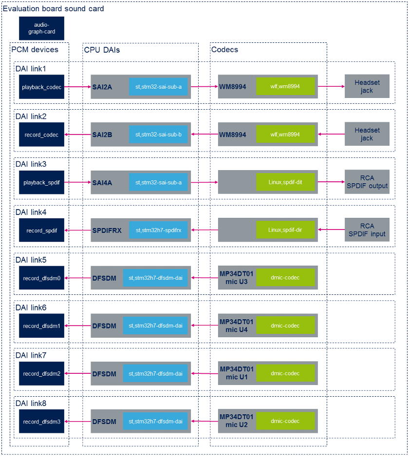
Static configuration
The extract below is from the STM32MP15 evaluation board device tree. Only the nodes associated to the sound card, and the most relevant properties are shown here. For example, the properties linking nodes to form the first DAI link are emphasized with green font.
/ * SOUNDCARD */
	sound {
		compatible = "audio-graph-card[1]";
		label = "STM32MP1-EV";			/* Sound card identified as STM32MP1EV in ALSA */
		routing =
			"AIF1CLK" , "MCLK1",
			"AIF2CLK" , "MCLK1",
			"IN1LN" , "MICBIAS2",
			"DMIC2DAT" , "MICBIAS1",
			"DMIC1DAT" , "MICBIAS1";
		dais = <&sai2a_port &sai2b_port &sai4a_port &spdifrx_port
			&dfsdm0_port &dfsdm1_port &dfsdm2_port &dfsdm3_port>;
	};

/ * CODECS */
	spdif_out: spdif-out {
		compatible = "linux,spdif-dit[4]";

		spdif_out_port: port@0 {
			spdif_out_endpoint: endpoint {
				remote-endpoint = <&sai4a_endpoint>;
			};
		};
	};

	spdif_in: spdif-in {
		compatible = "linux,spdif-dir[5]";
		spdif_in_port: port@0 {
			spdif_in_endpoint: endpoint {
				remote-endpoint = <&spdifrx_endpoint>;
			};
		};
	};

	dmic0: dmic@0 {
		compatible = "dmic-codec";
		port {
			dmic0_endpoint: endpoint {
				remote-endpoint = <&dfsdm_endpoint0>;
			};
		};
	};

	dmic1: dmic@1 {
		compatible = "dmic-codec";
		port {
			dmic1_endpoint: endpoint {
				remote-endpoint = <&dfsdm_endpoint1>;
			};
		};
	};

	dmic2: dmic@2 {
		compatible = "dmic-codec";
		port {
			dmic2_endpoint: endpoint {
				remote-endpoint = <&dfsdm_endpoint2>;
			};
		};
	};

	dmic3: dmic@3 {
		compatible = "dmic-codec";
		port {
			dmic3_endpoint: endpoint {
				remote-endpoint = <&dfsdm_endpoint3>;
			};
		};
	};
};

&i2c2 {
	wm8994: wm8994@1b {
		compatible = "wlf,wm8994";
		...
		clocks = <&sai2a>;
		clock-names = "MCLK1";

		ports {
			#address-cells = <1>;
			#size-cells = <0>;

			wm8994_tx_port: port@0 {
				wm8994_tx_endpoint: endpoint {
					remote-endpoint = <&sai2a_endpoint>;
				};
			};

			wm8994_rx_port: port@1 {
				wm8994_rx_endpoint: endpoint {
					remote-endpoint = <&sai2b_endpoint>;
				};
			};
		};
	};
};

/* CPU DAIS */
&sai2 {
	clocks = <&rcc SAI2>, <&rcc PLL3_Q>, <&rcc PLL4_Q>;
	pinctrl-names = "default", "sleep";
	pinctrl-0 = <&sai2a_pins_a>, <&sai2b_pins_a>;
	pinctrl-1 = <&sai2a_sleep_pins_a>, <&sai2b_sleep_pins_a>;
	clock-names = "pclk", "x8k", "x11k";

	sai2a: audio-controller@4400b004 {
		compatible = "st,stm32-sai-sub-a";
		dma-names = "tx";				/* SAI set as transmitter */
		clocks = <&rcc SAI2_K>;
		clock-names = "sai_ck";

		sai2a_port: port@0 {
			sai2a_endpoint: endpoint {
				remote-endpoint = <&wm8994_tx_endpoint>;
				format = "i2s";
				mclk-fs = <256>;		/* SAI is master clock provider */
			};
		};
	};

	sai2b: audio-controller@4400b024 {
		compatible = "st,stm32-sai-sub-b";
		dma-names = "rx";				/* SAI set as receiver */
		clocks = <&rcc SAI2_K>, <&sai2a>;
		clock-names = "sai_ck", "MCLK";

		sai2b_port: port@0 {
			sai2b_endpoint: endpoint {
				remote-endpoint = <&wm8994_rx_endpoint>;
				format = "i2s";
				mclk-fs = <256>;		/* SAI is master clock provider */
			};
		};
	};
};

&sai4 {
	clocks = <&rcc SAI4>, <&rcc PLL3_Q>, <&rcc PLL4_Q>;
	clock-names = "pclk", "x8k", "x11k";

	sai4a: audio-controller@50027004 {
		compatible = "st,stm32-sai-sub-a";
		dma-names = "tx";
		st,iec60958;					/* SAI configured for S/PDIF protocol*/
		pinctrl-names = "default", "sleep";
		pinctrl-0 = <&sai4a_pins_a>;
		pinctrl-1 = <&sai4a_sleep_pins_a>;
 		clocks = <&rcc SAI4_K>;
		clock-names = "sai_ck";

		sai4a_port: port@0 {
			sai4a_endpoint: endpoint {
				remote-endpoint = <&spdif_out_endpoint>;
			};
		};
	};
};

&spdifrx {
 	compatible = "st,stm32h7-spdifrx";
 	pinctrl-names = "default", "sleep";
	pinctrl-0 = <&spdifrx_pins_a>;
	pinctrl-1 = <&spdifrx_sleep_pins_a>;

	spdifrx_port: port@0 {
		spdifrx_endpoint: endpoint {
			remote-endpoint = <&spdif_in_endpoint>;
		};
	};

&dfsdm {
	compatible = "st,stm32mp1-dfsdm";
	pinctrl-names = "default", "sleep";
	pinctrl-0 = <&dfsdm_clkout_pins_a
		     &dfsdm_data1_pins_a &dfsdm_data3_pins_a>;
	pinctrl-1 = <&dfsdm_clkout_sleep_pins_a
		     &dfsdm_data1_sleep_pins_a &dfsdm_data3_sleep_pins_a>;
	spi-max-frequency = <2048000>;

	clocks = <&rcc DFSDM_K>, <&rcc ADFSDM_K>;
	clock-names = "dfsdm", "audio";

	dfsdm0: filter@0 {
		compatible = "st,stm32-dfsdm-dmic";
		st,adc-channels = <3>; 	 	 	/* Use channel 3, shared with mic U3 */
		st,adc-channel-names = "dmic_u1"; 	/* Left mic U1 associated with Right mic U3, for stereo */
		st,adc-channel-types = "SPI_R"; 	/* Rising edge for left channel */
		st,adc-channel-clk-src = "CLKOUT"; 	/* CKOUT clocks the microphones */
		st,filter-order = <3>;

		asoc_pdm0: dfsdm-dai {
			compatible = "st,stm32h7-dfsdm-dai";
			#sound-dai-cells = <0>;
			io-channels = <&dfsdm0 0>;
			cpu_port0: port {
				dfsdm_endpoint0: endpoint {
					remote-endpoint = <&dmic0_endpoint>;
				};
			};
		};
	};

	dfsdm1: filter@1 {
		compatible = "st,stm32-dfsdm-dmic";
		st,adc-channels = <1>;
		st,adc-channel-names = "dmic_u2";
		st,adc-channel-types = "SPI_F";
		st,adc-channel-clk-src = "CLKOUT";
		st,filter-order = <3>;

		asoc_pdm1: dfsdm-dai {
			compatible = "st,stm32h7-dfsdm-dai";
			#sound-dai-cells = <0>;
			io-channels = <&dfsdm1 0>;
			cpu_port1: port {
				dfsdm_endpoint1: endpoint {
					remote-endpoint = <&dmic1_endpoint>;
				};
			};
		};
	};

	dfsdm2: filter@2 {
		compatible = "st,stm32-dfsdm-dmic";
		st,adc-channels = <3>; 	 	 	/* Use channel 3, shared with mic U1 */
		st,adc-channel-names = "dmic_u3"; 	/* Right mic U3 associated with Left mic U1, for stereo */
		st,adc-channel-types = "SPI_F"; 	/* Falling edge for Right channel */
		st,adc-channel-clk-src = "CLKOUT";
		st,filter-order = <3>;

		asoc_pdm2: dfsdm-dai {
			compatible = "st,stm32h7-dfsdm-dai";
			#sound-dai-cells = <0>;
			io-channels = <&dfsdm2 0>;
			cpu_port2: port {
				dfsdm_endpoint2: endpoint {
					remote-endpoint = <&dmic2_endpoint>;
				};
			};
		};
	};

	dfsdm3: filter@3 {
		compatible = "st,stm32-dfsdm-dmic";
		st,adc-channels = <1>;
		st,adc-channel-names = "dmic_u4";
		st,adc-channel-types = "SPI_R";
		st,adc-channel-clk-src = "CLKOUT";
		st,filter-order = <3>;

		asoc_pdm3: dfsdm-dai {
			compatible = "st,stm32h7-dfsdm-dai";
			#sound-dai-cells = <0>;
			io-channels = <&dfsdm3 0>;
			cpu_port3: port {
				dfsdm_endpoint3: endpoint {
					remote-endpoint = <&dmic3_endpoint>;
				};
			};
		};
	};
};
The card-specific alsa-lib configuration file for STMP32MP15 Evaluation board is /usr/share/alsa/cards/STM32MP1EV.conf.
Dynamic configuration
The table below gives an overview of the controls allowing configuration of the STM32MPU evaluation board "sound" sound card.
| audio device | CPU DAI | codec |
|---|---|---|
| playback_codec | no controls available | configure codec output path |
| record_codec | no controls available | configure codec input path |
| playback_spdif | configure iec958 | no controls available |
| record_spdif | configure SPDFIRX input path | no controls available |
Wolfson wm8994 output configuration
- Control commands to configure aif1 interface to headset output (HPOUT1L/R) path, on wm8994 codec:
amixer -c STM32MP1EV cset name='AIF1DAC1 Volume' '96' '96'
amixer -c STM32MP1EV cset name='Headphone Volume' '63' '63'
amixer -c STM32MP1EV cset name='DAC1 Volume' '50' '50'
amixer -c STM32MP1EV cset name='DAC1L Mixer AIF1.1 Switch' 'on'
amixer -c STM32MP1EV cset name='DAC1R Mixer AIF1.1 Switch' 'on'
amixer -c STM32MP1EV cset name='DAC1 Switch' 'on' 'on'
amixer -c STM32MP1EV cset name='Left Output Mixer DAC Switch' 'on'
amixer -c STM32MP1EV cset name='Right Output Mixer DAC Switch' 'on'
amixer -c STM32MP1EV cset name='Headphone Switch' 'on' 'on'
- Control commands to configure aif1 interface to speaker output (SPKOUTL/RP) path, on wm8994 codec:
amixer -c STM32MP1EV cset name='AIF1DAC1 Volume' '96' '96'
amixer -c STM32MP1EV cset name='DAC1L Mixer AIF1.1 Switch' 'on'
amixer -c STM32MP1EV cset name='DAC1R Mixer AIF1.1 Switch' 'on'
amixer -c STM32MP1EV cset name='DAC1 Switch' 'on','on'
amixer -c STM32MP1EV cset name='DAC1 Volume' '96','96'
amixer -c STM32MP1EV cset name='SPKL DAC1 Volume' '50' '50'
amixer -c STM32MP1EV cset name='SPKR DAC1 Volume' '50' '50'
amixer -c STM32MP1EV cset name='SPKL DAC1 Switch' 'on'
amixer -c STM32MP1EV cset name='SPKR DAC1 Switch' 'on'
amixer -c STM32MP1EV cset name='SPKL Output Switch' 'on'
amixer -c STM32MP1EV cset name='SPKR Output Switch' 'on'
amixer -c STM32MP1EV cset name='Speaker Mode' 'Class AB'
amixer -c STM32MP1EV cset name='Speaker Volume' '50' '50'
amixer -c STM32MP1EV cset name='Speaker Mixer Volume' 3
amixer -c STM32MP1EV cset name='Speaker Reference' 0
amixer -c STM32MP1EV cset name='Speaker Switch' 'on'
Wolfson wm8994 input configuration
- Control commands to configure headset microphone input (IN1LN) to aif2 interface, on wm8994 codec:
amixer -c STM32MP1EV cset name='IN1L PGA IN1LN Switch' 'on'
amixer -c STM32MP1EV cset name='IN1L PGA IN1LP Switch' 'off'
amixer -c STM32MP1EV cset name='IN1L Volume' '25'
amixer -c STM32MP1EV cset name='IN1L Switch' 'on'
amixer -c STM32MP1EV cset name='MIXINL IN1L Switch' 'on'
amixer -c STM32MP1EV cset name='MIXINL IN1L Volume' '1'
amixer -c STM32MP1EV cset name='MIXINL IN1LP Volume' '0'
amixer -c STM32MP1EV cset name='AIF1ADCL Source' 'Left'
amixer -c STM32MP1EV cset name='ADCL Mux' 'ADC'
amixer -c STM32MP1EV cset name='DAC2 Left Sidetone Volume' '12'
amixer -c STM32MP1EV cset name='DAC2 Right Sidetone Volume' '12'
amixer -c STM32MP1EV cset name='AIF2DAC2L Mixer Left Sidetone Switch' 'on'
amixer -c STM32MP1EV cset name='AIF2DAC2R Mixer Right Sidetone Switch' 'on'
amixer -c STM32MP1EV cset name='DAC2 Volume' '96' '96'
amixer -c STM32MP1EV cset name='DAC2 Switch' 'on' 'on'
amixer -c STM32MP1EV cset name='AIF2ADC Volume' '96' '96'
amixer -c STM32MP1EV cset name='AIF2ADC Mux' 'AIF2ADCDAT'
amixer -c STM32MP1EV cset name='AIF2 Boost Volume' '1'
amixer -c STM32MP1EV cset name='ADC OSR' 'Low Power'
SPDFIRX input configuration
- Control commands to configure rx1 input path on SPDFIRX:
amixer -c STM32MP1EV cset name='SPDIFRX input' 1
STM32MP15 disco board sound card configuration
Sound card overview
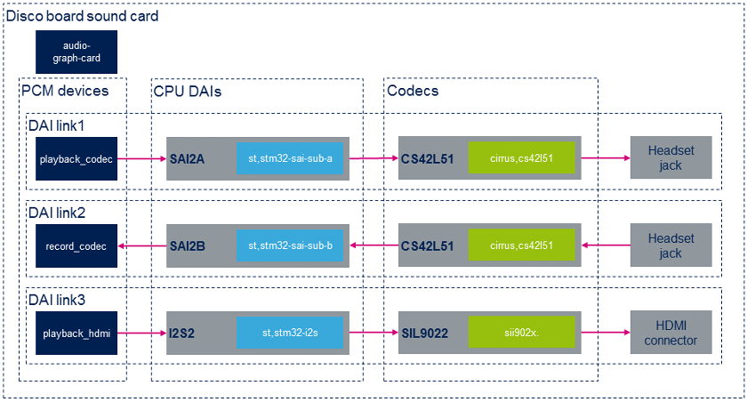
Static configuration
The extract below is from the STM32MP15 disco board device tree. Only the nodes associated to the sound card, and the most relevant properties are shown here. As an example, the properties linking nodes to form the first DAI link are emphasized with green font.
/ {
/ * SOUNDCARD */
sound {
compatible = "audio-graph-card";
label = "STM32MP1-DK"; /* Sound card identified as STM32MP1DK in ALSA */
routing =
"Playback" , "MCLK",
"Capture" , "MCLK",
"MICL" , "Mic Bias";
dais = <&sai2a_port &sai2b_port &i2s2_port>;
status = "okay";
};
};
/ * CODECS */
&i2c1 {
cs42l51: cs42l51@4a {
compatible = "cirrus,cs42l51";
...
clocks = <&sai2a>;
clock-names = "MCLK";
cs42l51_port: port {
#address-cells = <1>;
#size-cells = <0>;
cs42l51_tx_endpoint: endpoint@0 {
reg = <0>;
remote-endpoint = <&sai2a_endpoint;
frame-master; /* codec is master */
bitclock-master;
};
cs42l51_rx_endpoint: endpoint@1 {
reg = <1>;
remote-endpoint = <&sai2b_endpoint>;
frame-master; /* codec is master */
bitclock-master;
};
};
};
hdmi-transmitter@39 {
compatible = "sil,sii9022";
...
ports {
#address-cells = <1>;
#size-cells = <0>;
port@0 {
reg = <0>;
sii9022_in: endpoint {
remote-endpoint = <<dc_ep0_out>;
};
};
port@1 {
reg = <1>;
sii9022_tx_endpoint: endpoint {
remote-endpoint = <&i2s2_endpoint>;
};
};
};
};
};
/* CPU DAIS */
&sai2 {
clocks = <&rcc SAI2>, <&rcc PLL3_Q>, <&rcc PLL3_Q>;
clock-names = "pclk", "x8k", "x11k";
pinctrl-names = "default", "sleep";
pinctrl-0 = <&sai2a_pins_a>, <&sai2b_pins_b>;
pinctrl-1 = <&sai2a_sleep_pins_a>, <&sai2b_sleep_pins_b>;
status = "okay";
sai2a: audio-controller@4400b004 {
compatible = "st,stm32-sai-sub-a";
#clock-cells = <0>;
dma-names = "tx"; /* SAI set as transmitter */
clocks = <&rcc SAI2_K>;
clock-names = "sai_ck";
sai2a_port: port {
sai2a_endpoint: endpoint {
remote-endpoint = <&cs42l51_tx_endpoint>;
format = "i2s";
mclk-fs = <256>;
dai-tdm-slot-num = <2>;
dai-tdm-slot-width = <32>;
};
};
};
sai2b: audio-controller@4400b024 {
dma-names = "rx"; /* SAI set as receiver */
st,sync = <&sai2a 2>; /* SAI2B is slave of SAI2A */
clocks = <&rcc SAI2_K>, <&sai2a>;
clock-names = "sai_ck", "MCLK";
sai2b_port: port {
sai2b_endpoint: endpoint {
remote-endpoint = <&cs42l51_rx_endpoint>;
format = "i2s";
mclk-fs = <256>;
dai-tdm-slot-num = <2>;
dai-tdm-slot-width = <32>;
};
};
};
};
&i2s2 {
clocks = <&rcc SPI2>, <&rcc SPI2_K>, <&rcc PLL3_Q>, <&rcc PLL4_Q>;
clock-names = "pclk", "i2sclk", "x8k", "x11k";
pinctrl-names = "default", "sleep";
pinctrl-0 = <&i2s2_pins_a>;
pinctrl-1 = <&i2s2_pins_sleep_a>;
status = "okay";
i2s2_port: port {
i2s2_endpoint: endpoint {
remote-endpoint = <&sii9022_tx_endpoint>;
format = "i2s";
mclk-fs = <256>;
};
};
};
The card-specific alsa-lib configuration file for STMP32MP15 Disco board is /usr/share/alsa/cards/STM32MP1DK.conf.
Dynamic configuration
The table below gives an overview of the controls allowing the configuration of the STM32MPU disco board sound card.
| audio device | CPU DAI | codec |
|---|---|---|
| playback_codec | no controls available | configure codec output path |
| record_codec | no controls available | configure codec input path |
| playback_hdmi | no controls available | no controls available |
Cirrus cs42l51 output configuration
- Control commands to configure the aif interface to headset output (AOUTA/B) path, on the cs42l51 codec:
amixer -c STM32MP1DK cset name='PCM Playback Switch' 'on','on'
amixer -c STM32MP1DK cset name='PCM Playback Volume' '63','63'
amixer -c STM32MP1DK cset name='Analog Playback Volume' '204','204'
amixer -c STM32MP1DK cset name='PCM channel mixer' 'L R'
Cirrus cs42l51 input configuration
- Control commands to configure headset microphone input (MICIN1/AIN3A) to the aif interface, on the cs42l51 codec:
amixer -c STM32MP1DK cset name='PGA-ADC Mux Left' '3'
amixer -c STM32MP1DK cset name='Mic Boost Volume' '1','1'
References
- ↑ 1.01.1 Documentation/devicetree/bindings/sound/audio-graph-card.txt| |}} Documentation/devicetree/bindings/sound/audio-graph-card.txt
- ↑ Documentation/devicetree/bindings/graph.txt| |}} Documentation/devicetree/bindings/graph.txt
- ↑ 3.03.13.2 asound.conf
- ↑ Documentation/devicetree/bindings/sound/spdif-transmitter.txt| |}} Documentation/devicetree/bindings/sound/spdif-transmitter.txt
- ↑ Documentation/devicetree/bindings/sound/spdif-receiver.txt| |}} Documentation/devicetree/bindings/sound/spdif-receiver.txt
<securetransclude src="ProtectedTemplate:PublicationRequestId" params="9884 | 2018-12-11 | PhilipS"></securetransclude>