SAI device tree configuration
目录
Article purpose
本文介绍如何在将 SAI internal peripheral 分配给 Linux® OS时对其进行配置。在这种情况下,它由 ALSA framework控制。
使用device tree 机制执行配置,该机制提供由SAI linux driver使用的SAI外围设备的硬件描述。
如果外围设备已分配给另一个执行上下文,请参阅 How to assign an internal peripheral to a runtime context 文章,以获取有关外围设备分配和配置的准则。
DT bindings documentation
STM32 SAI设备树绑定 [1] 本文档介绍了所有必需的和可选的配置属性。
DT configuration
该硬件描述是STM32微处理器设备树文件(扩展名为.dtsi)和板子设备树文件(扩展名为.dts)的组合。 有关设备树文件分割的说明,请参见Device tree。
通过Linux ® 内核ALSA框架,SAI用作声卡的组件。 与声卡相关的设备树节点在board device tree中进行了描述。
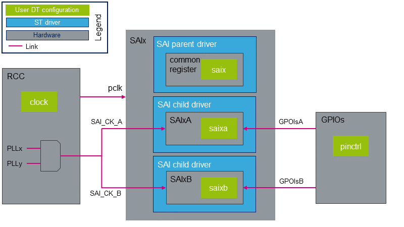
STM32 SAI外设包括两个共享公共资源的独立音频子块。 SAI设备树节点反映了这种体系结构,如下面的SAI DT示例所示。
&saix {
	/* SAIx parent node. Configure common ressources  */
	clock-names = "pclk", "x8k", "x11k"; /* Peripheral and parent clock configuration.  */
	...

	saixa {
		/* child node. Configure ressources dedicated to SAIxA subblock */
		clock-names = "sai_ck"; /* SAIxA kernel clock confguration.  */
		pinctrl-names = "default"; /* GPIOsA configuration.  */
		...
	};

	saixb {
		/* child node. Configure ressources dedicated to SAIxB subblock */
		clock-names = "sai_ck"; /* SAIxB kernel clock confguration.  */
		pinctrl-names = "default"; /* GPIOsB configuration.  */
		...
	};
};
STM32CubeMX 可用于生成板卡设备树。有关更多详细信息,请参考How to configure the DT using STM32CubeMX。
DT configuration (STM32 level)
SAI节点在STM32微处理器设备树中声明。它们描述了硬件参数,例如寄存器地址,中断和DMA。 对于给定的STM32MPU,这组属性可能不会改变。 对于STM32MP1,对应的DT文件为stm32mp157c.dtsi [2].
| 该设备树部分与STM32微处理器有关。它应保持原样,而不应由最终用户修改。 |
DT configuration (board level)
SAI配置是否取决于板,是否连接到外部组件(例如音频编解码器)。 SAI与其他组件之间的链接定义了声卡。 必须在主板设备树中配置此声卡。有关各种STM32MPU板上SAI配置的示例,请参考soundcard configuration。
DT configuration examples
本章详细介绍高级SAI配置。 这些示例基于 STM32MP1 boards SAI用例。 相应的设备树可以在 soundcard 文章中找到。
| In this chapter, "SAI" stands for an SAI subblock, SAIxA or SAIxB. |
Setting SAI as a master clock provider
SAI外设可以通过mclk输出引脚为外部组件 (例如编解码器)提供时钟。 在这种情况下,它充当主时钟(mclk)提供程序。下面的DT示例提供了一个作为mclk provider的SAI配置示例。 在此示例中,编解码器驱动程序支持基于ASoC DAPM机制的mclk输入。 如果不是这种情况,则必须调整编解码器驱动程序。这可以通过将DAPM时钟供应小部件添加到编解码器驱动程序来实现。 所需的DAPM时钟供应小部件的示例可以在Cirrus CS42L51编解码器源代码[3]. 在下面的设备树示例中,编解码器DAPM时钟窗口小部件名为“MCLKX”。
为了允许mclk激活/停用,必须在DT中定义DAPM路由。此路由在sound节点中定义,如下所示。
soundcard {
	routing =
		"Playback" , "MCLKX", /* Set a route between "MCLKX" and "playback" widgets */
		"Capture" , "MCLKX";
	...
};

codec: {
	clocks = <&sai2a>;     /* The codec is a consumer of SAI2A master clock */
	clock-names = "MCLKX"; /* Feed MCLKX codec clock with SAI2A master clock provider */
	...
};

&sai2 {
	...

	sai2a: audio-controller@4400b004 {
		#clock-cells = <0>; /* Set SAI2A as master clock provider */
		...
		sai2a_endpoint: endpoint {
			mclk-fs = <256>; /* Set mclk/fs ratio. (256 or 512) */
		};
	};
};
Sharing master clock between two SAIs
将SAI设置为主时钟提供者时,另一个SAI可以共享该主时钟。 这可以通过通过DT配置将SAI设置为mclk使用者来实现。 这意味着mclk使用者SAI可以请求根据其自己的音频流采样率更改mclk速率。 这意味着当使用两个SAI子块时,音频采样率必须相同。
&sai2 {
	...

	sai2a: audio-controller@4400b004 {
		#clock-cells = <0>; /* Set SAI2A as master clock provider */
		...
	};

	sai2b: audio-controller@4400b024 {
		clocks = <&rcc SAI2_K>, <&sai2a>; /* SAI2B is a consumer of SAI2A master clock */
		clock-names = "sai_ck", "MCLK";   /* Feed SAI2B MCLK clock with SAI2A master clock provider */
		...
		sai2b_endpoint: endpoint {
			mclk-fs = <256>; /* Set mclk/fs ratio. (256 or 512) */
		};
	};
};
Sharing the codec interface between two SAIs
通过共享I2S总线(即FS和SCK时钟),两个SAI可以连接到同一编解码器接口。
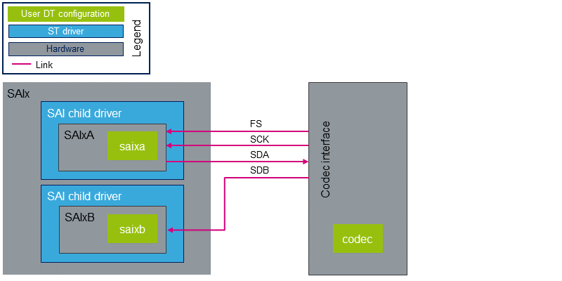
在这种情况下:
- 编解码器必须是I2S总线上的主机。
- 总线时钟仅连接一个SAI。 另一个SAI必须配置为连接到总线的SAI的从设备。
- I2S总线 I/O 引脚必须在父级进行管理,以便无论正在运行的SAI如何激活相应的引脚。
从ASoC的角度来看:
必须将两个CPU DAI连接到同一编解码器DAI。 ASoC音频图形卡本身不支持这种拓扑。 实际上,当音频图形卡解析编解码器节点时,它期望找到与端点索引匹配的DAI接口索引。 一种解决方法是在编解码器驱动程序中实现of_xlate_dai_id回调,以允许对两个端点使用相同的DAI接口。可以在下面或在Cirrus CS42L51编解码器源代码中找到代码示例。[3].
- 代码示例
static int codec_of_xlate_dai_id(struct snd_soc_component *component,
				   struct device_node *endpoint)
{
	/* return dai id 0, whatever the endpoint index */
	return 0;
}
- DT example
codec {
	...
	codec_port {
		codec_tx_endpoint {
			remote-endpoint = <&sai2a_endpoint>;
			frame-master;    /* Set codec as master of SAI2A for FS clock. */
			bitclock-master; /* Set codec as master of SAI2A for SCK clock. */
		};

		codec_rx_endpoint { /* Second endpoint mapped on codec DAI 0 via of_xlate */
			remote-endpoint = <&sai2b_endpoint>;
			frame-master;    /* Set codec as master of SAI2B for FS clock. */
			bitclock-master; /* Set codec as master of SAI2B for SCK clock. */
		};
	};
};

&sai2 {
	pinctrl-names = "default", "sleep"; /* Defines SAI2A/B GPIOs at parent level. */
	pinctrl-0 = <&sai2a_pins_a>, <&sai2b_pins_b>;
	pinctrl-1 = <&sai2a_sleep_pins_a>, <&sai2b_sleep_pins_b>;
	...

	sai2a: audio-controller@4400b004 {
		remote-endpoint = <&codec_tx_endpoint>;
		...
	};

	sai2b: audio-controller@4400b024 {
		remote-endpoint = <&codec_rx_endpoint>;
		st,sync = <&sai2a 2>; /* Set SAI2B as slave of SAI2A. */
	};
};
How to configure the DT using STM32CubeMX
The STM32CubeMX tool can be used to configure the STM32MPU device and get the corresponding platform configuration device tree files.
The STM32CubeMX may not support all the properties described in the above DT bindings documentation paragraph. If so, the tool inserts user sections in the generated device tree. These sections can then be edited to add some properties and they are preserved from one generation to another. Refer to STM32CubeMX user manual for further information.
| The STM32CubeMX does not allow the generation of all the nodes required to configure a soundcard. The soundcard node and the codec nodes have to be filled manually through user sections. |